Original Norton DOHC Cambox(s) Stripdown - Part 2: July 2019
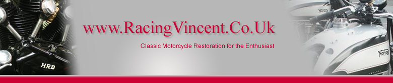
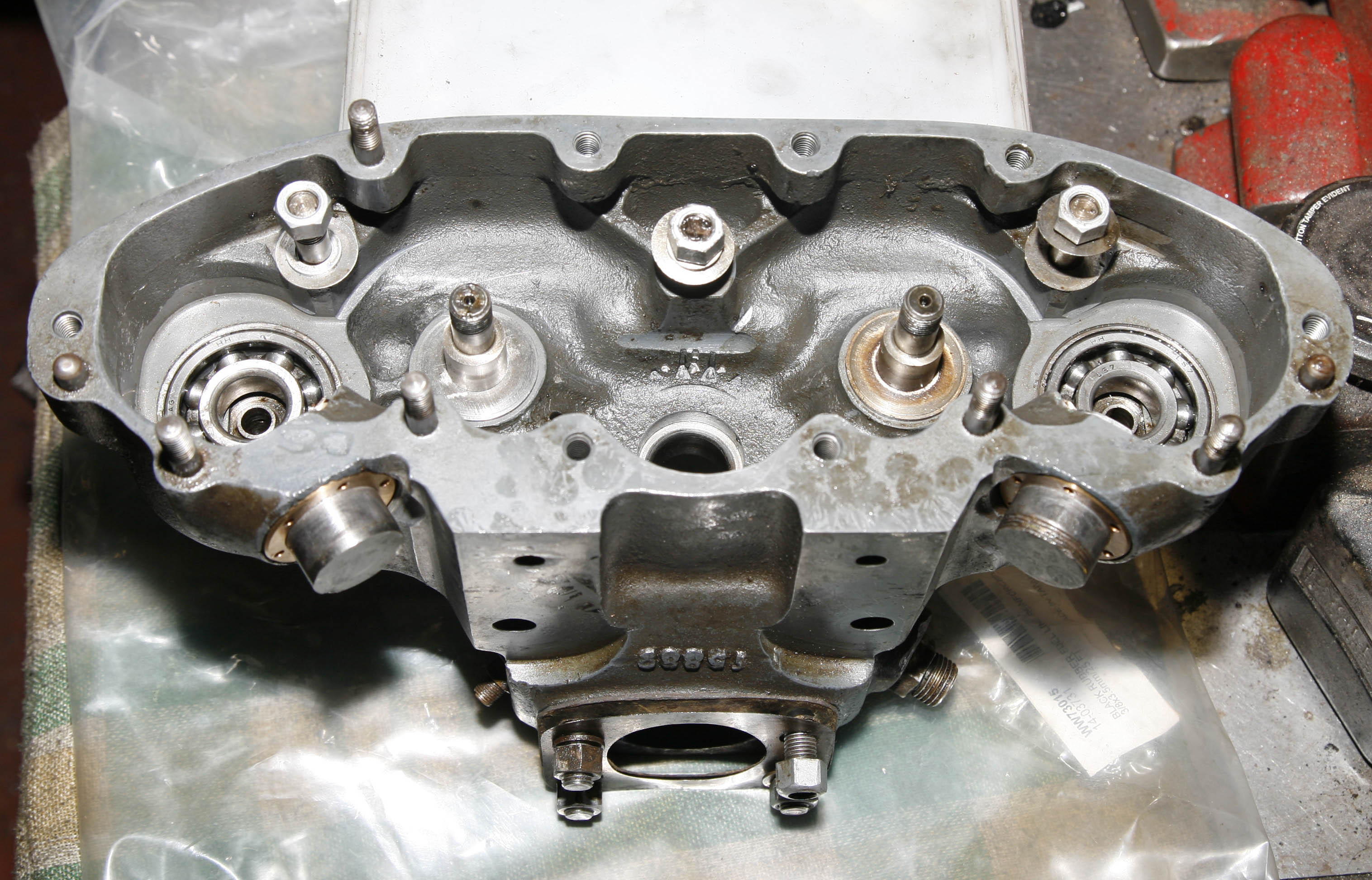
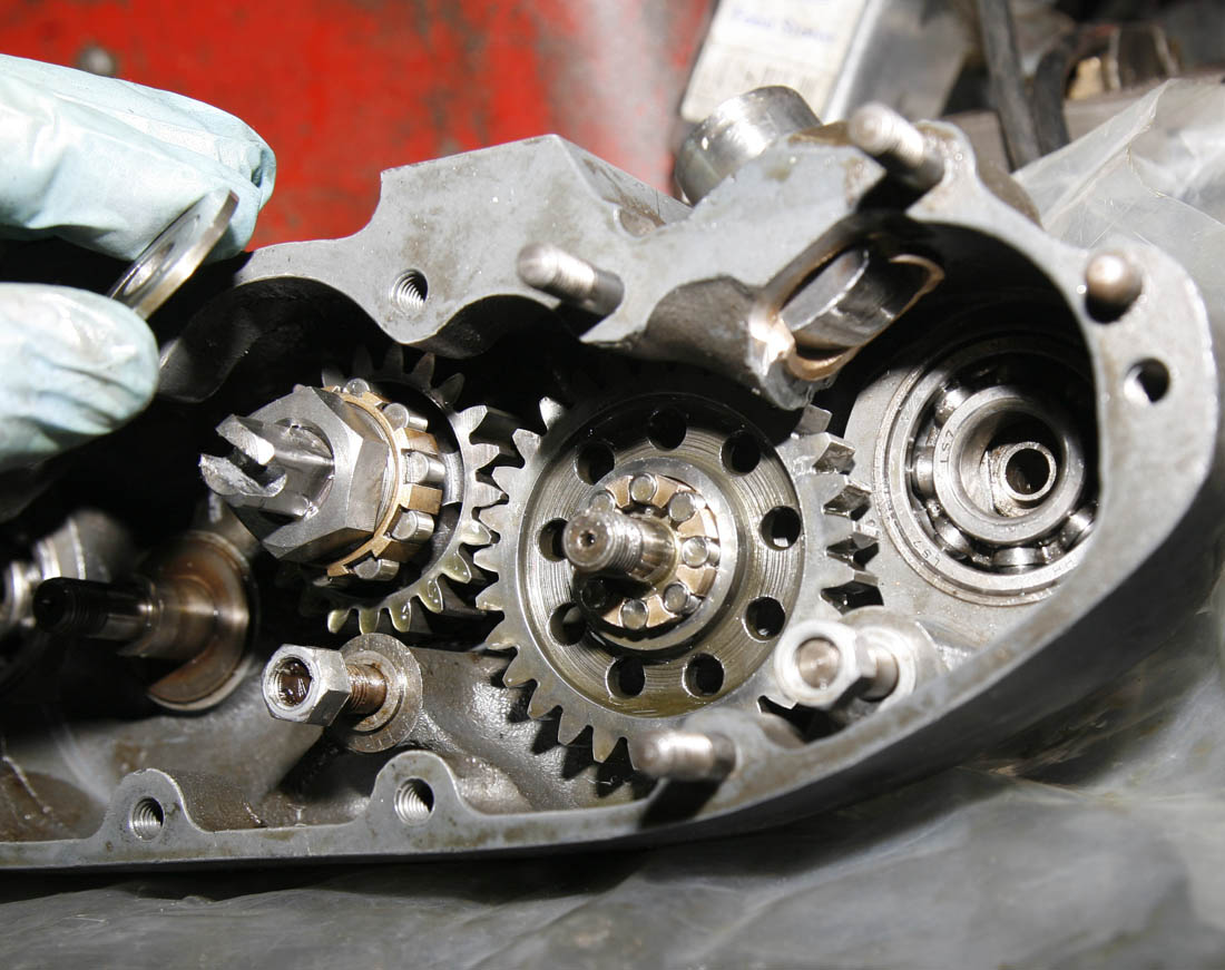
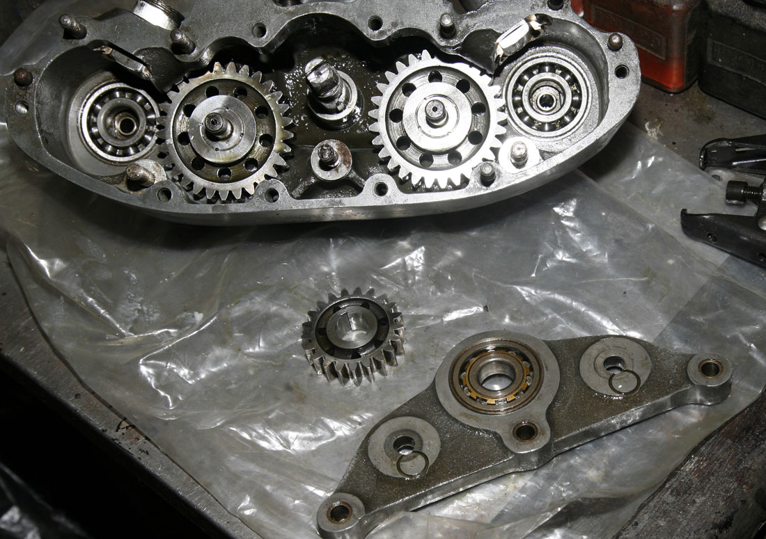
A reminder where we had got to at the end of the previous article - the camshafts had been removed, along with the outrigger bearing and idler wheels - all of which were in good condition, and just needed a thorough cleaning.
Next task - tolook at the old Pusher bearing replacement
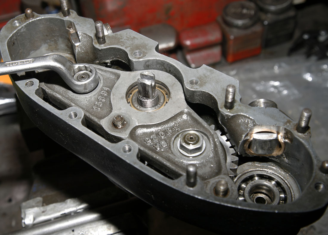
In the previoius article I had covered the first part of the stripdown of this very original and unmolested mid 1950's DOHC cambox - which had got it to the point where the camshafts had been removed, along with the outrigger casting and the idler gears.
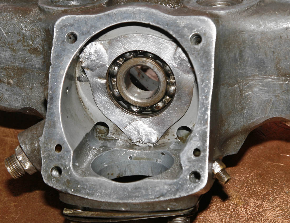
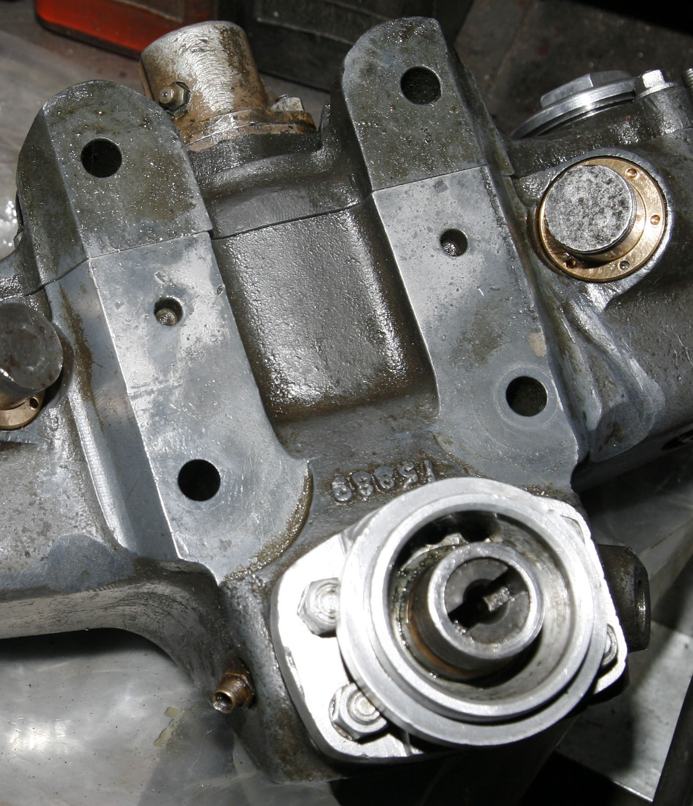
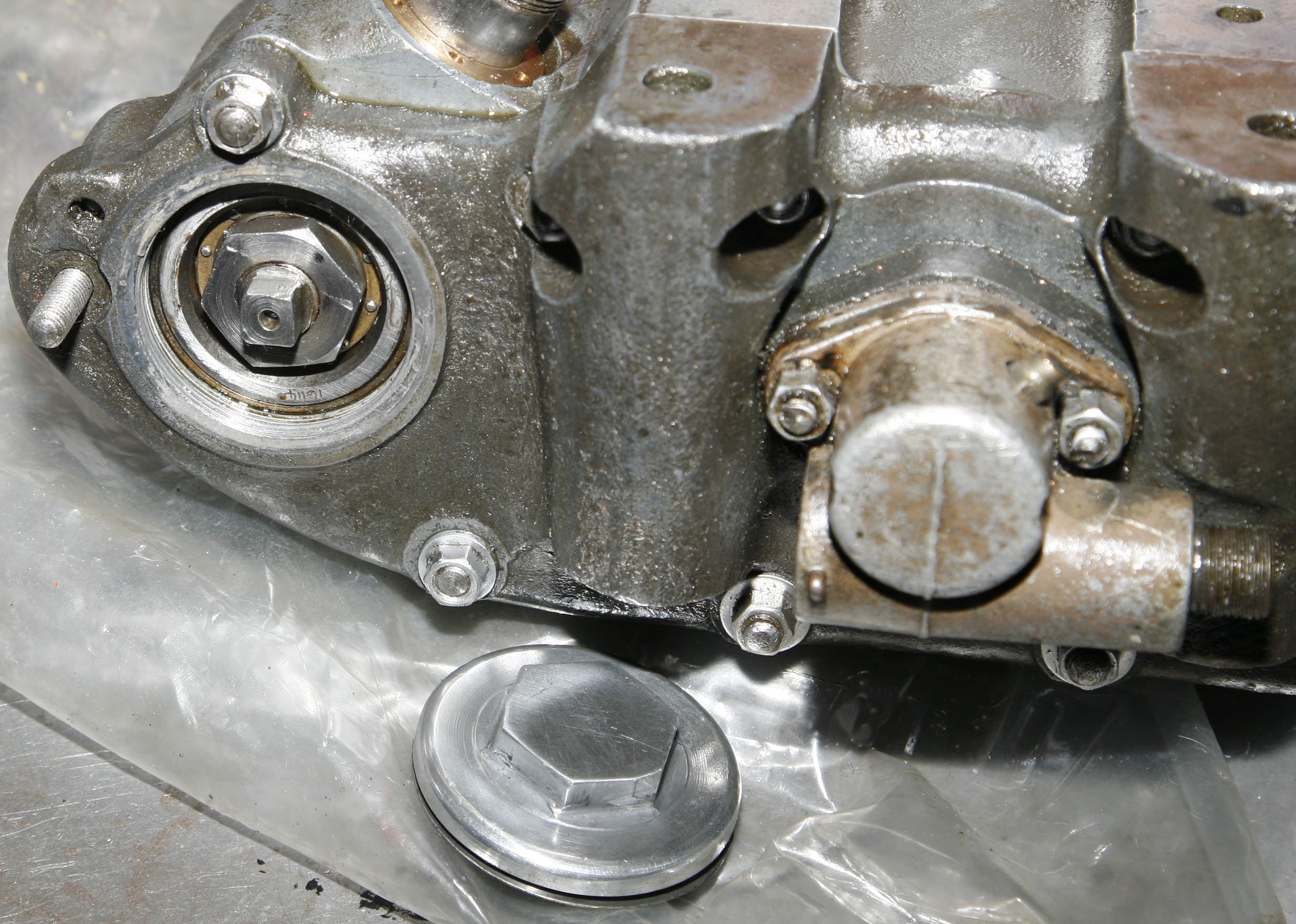
The most obvious next step would be to remove the central bevel shaft assembly - which could be seen still in place in the accompanyning photo on the left. However, having had a close inspection of the rear roller bearing, the front bevel gears and the gear wheel (that drives the idler gears) I was having doubts to as if this was really necessary?
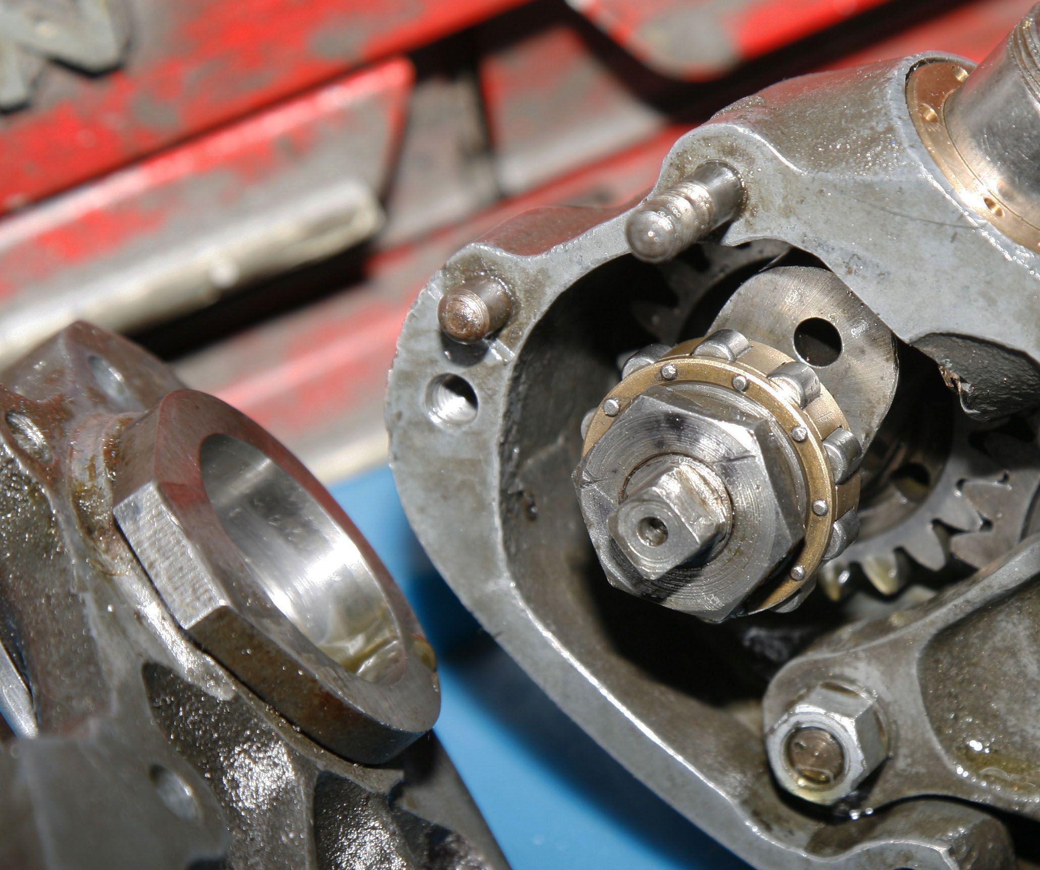
True, I could nott get a good look at the main front bevel bearing . .. which would be single row ball bearing, as it sat behind the big front bevel gear - but I had had it soaking in degreasing oil for a couple of weeks and it was spinning nice and freely now with no obvious side play or rumbling. I know from past experience of SOHC cambox's that these shafts are tightened up very securely (one of the few areas of a Norton engine build where I will use a torque wrench, rather than relying on just 'feel', as it requires +50lb per sq inch), and can sometimes be difficult to undo, particularly as the rear nut is a LH thread and needs a very firm grip on the square of the shaft. I had no problem doing this, but was wondering if it was really worthwhile - as I could clean pretty much all of the assembly in situ - other than the back of drive gear, where poking my finger around the back, I could feel a bit of the treacly old Castrol R still adhering to it.
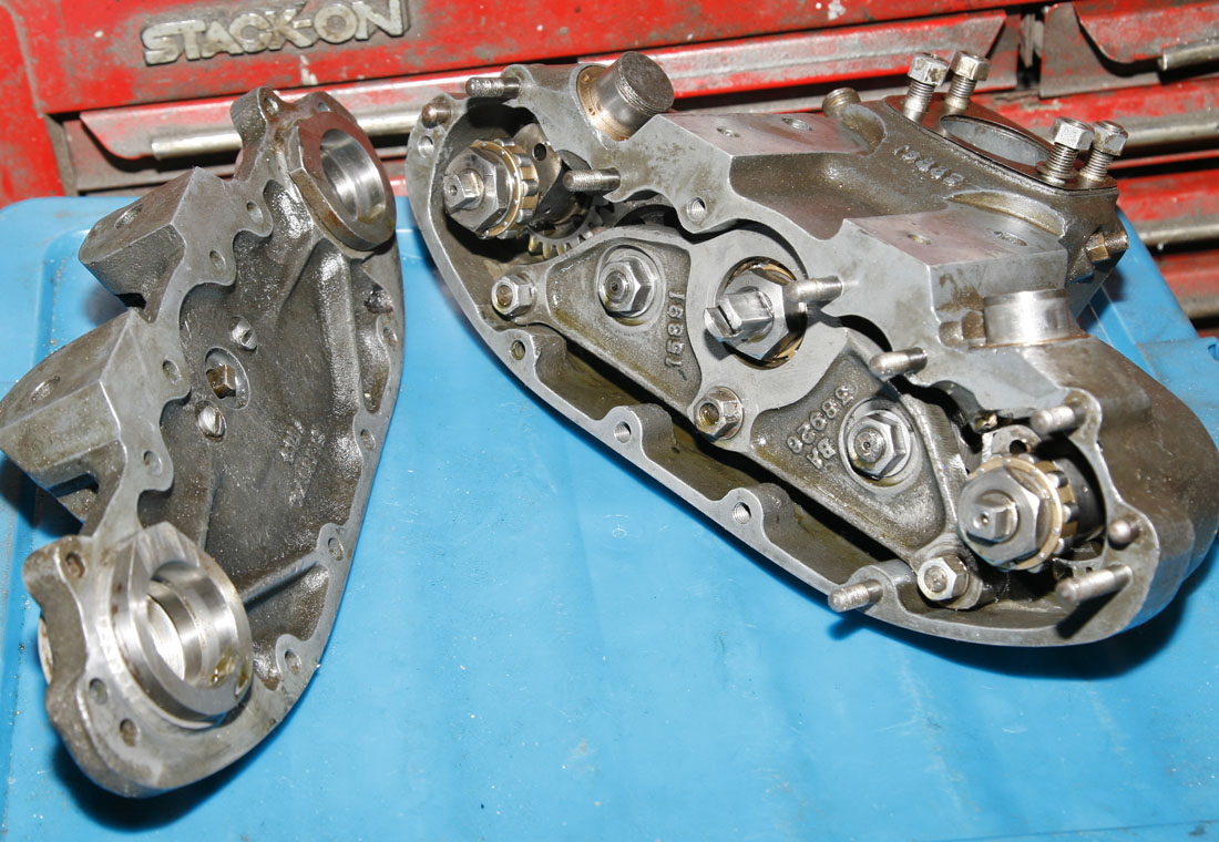
So having got to this point by early June 2019, while pondering the benefits of taking the central shaft apart - I switched tack's and decided to look at the replacement of the Pusher bearings - the main overhaul task I knew needed to be tackled on this cambox when I purchased it.
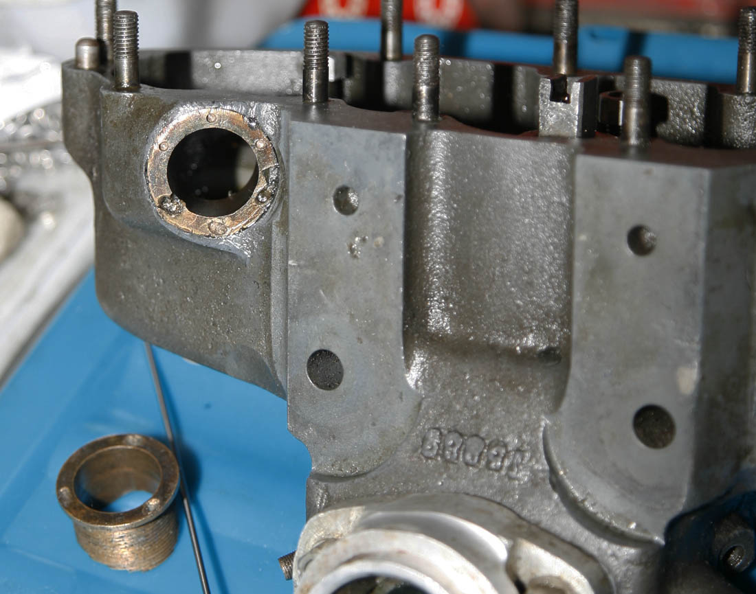
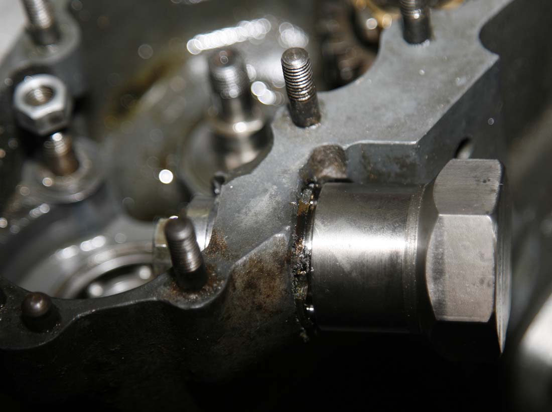
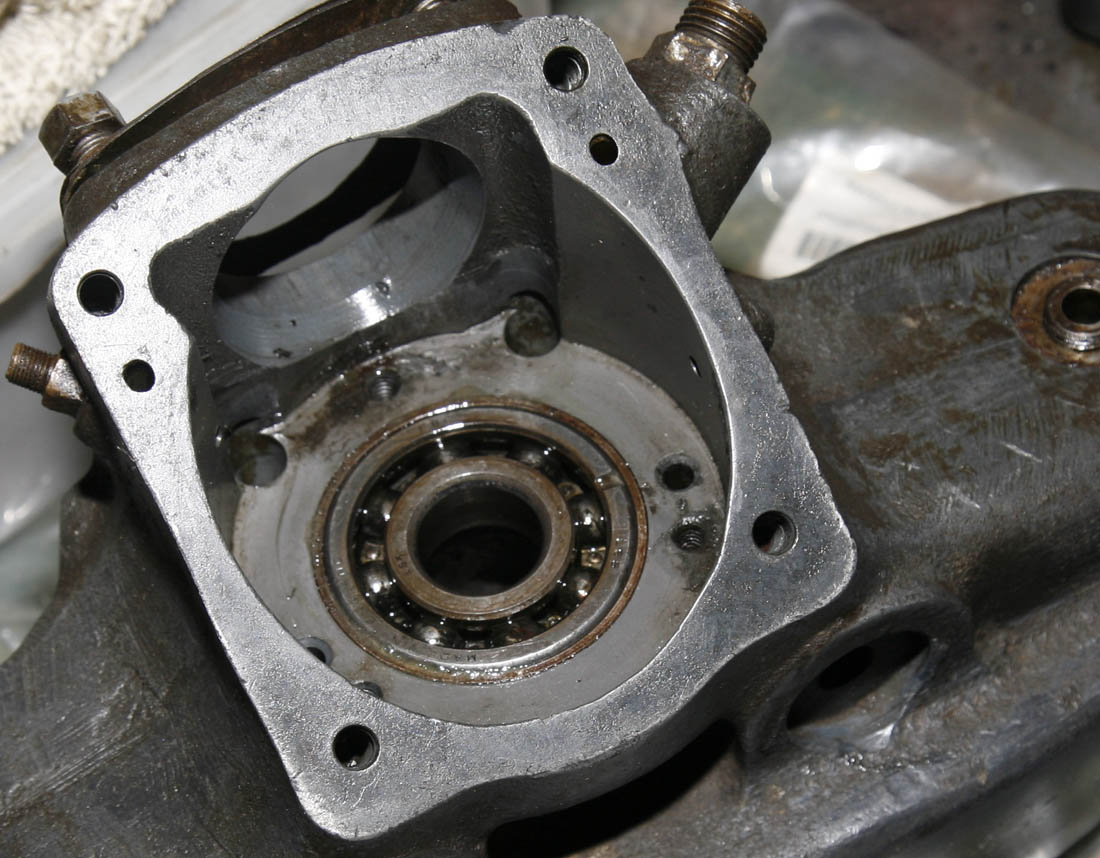
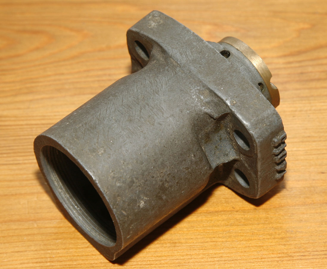
This picture shows the underside of DOHC cambox shell, with the exhaust camshaft pusher bearing visible and still in place in the housing. Clearly the previous owner had tried to remove it - but this is a difficult bearing to remove without special tools - it sitting flush with the shell and the only means of purchase are small blind holes in the bearing around its circumference, about 4mm in depth. As can be seen in this photo - it looks like the previous owners 'specialist' tool had been a punch (ahem!)- as many would, and it had not budged - instead chewing some of the holes.
Luckily, this bearing was a '6 hole' type and some of the remaining holes were still in reasonable unmolested condition. In the small box of bits that came with this cambox when I purchased it, was another old bearing - which I assume was the inlet side bearing that had been successfully removed. Interestingly - this bearing has just 3 holes, but although they were a bit chewed - it seemed to have come out ok
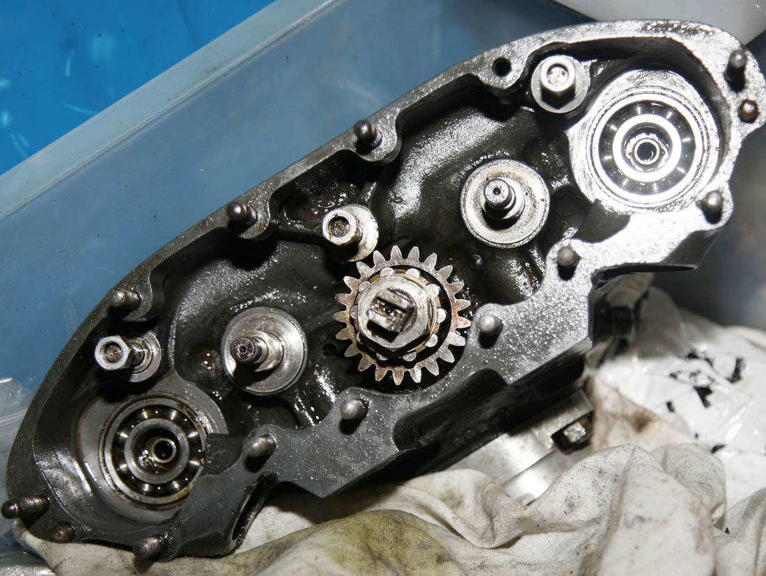
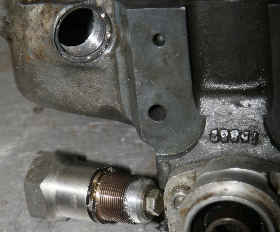
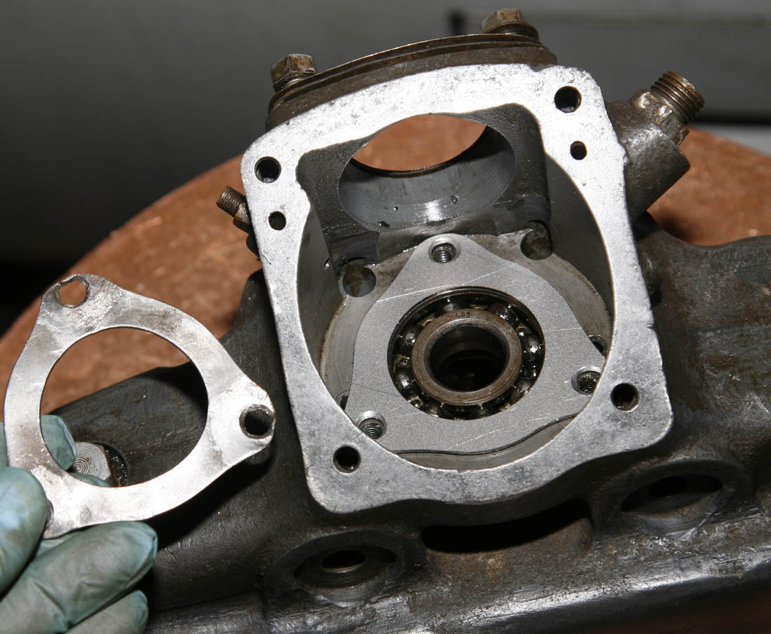
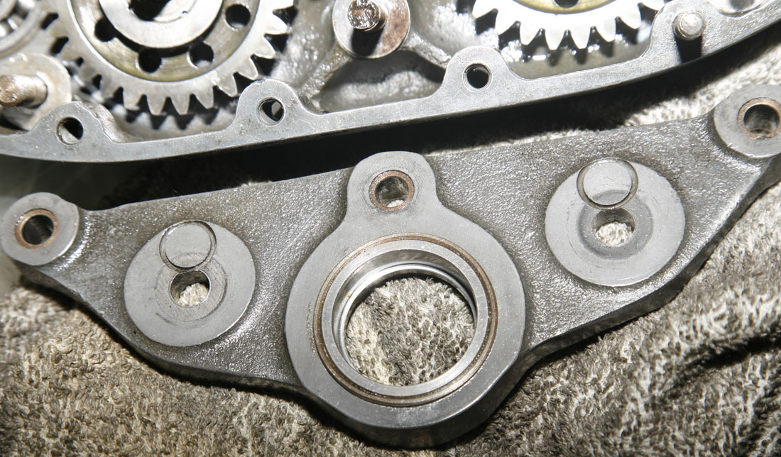
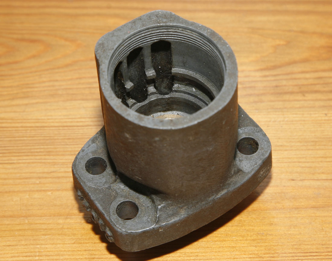
As a useful comparison, this is the pusher bearing housing on Inlet side, where the bearing had already been removed by the previous owner.
As can be seen, there is a machined recess first, which the lip of the bearing sits in and will be fully flush when screwed home. Then beneath the recess is a deep threaded area - which the phosphor bronze bearing is screwed into.
The Issue of Removing and Replacing Old Pusher Bearings
Only just visible in the photograph above on the right - where the Inlet side pusher bearing thread is showing - at the base of the thread is a scolloped area - where the bronze bearing has a curved scollop machined from it, once in place and fully screwed home. This is done so that the cam lobe does not foul the bearing at its highest point of lift as it rotates. As this scollop can only be machined on the bearing when the bearing has been fully screwed home - it follows that the bearing may be left with some sharp protruding edges from teh cutting tool - with the possible issue that on removing the old bearing - it can damage the housing thread with the sharp edges. As you can see - this thread looks fine, but I was worried that for the knackered exhaust bearing - as well as now being 'well seized' into the cambox shell, it might also damage the thread in the process of being removed.
As a footnote - although the use of cam 'pushers' is still considered 'current' technology for high performance engines over 50 years on from when this cambox first appeared, I cannot help but think this is the one weak part of design on the Norton DOHC cambox. The main difference beween the Norton DOHC cambox and modern design is - this cambox was almost a seperate external unit from the main engine below - with its own oil feed been fed from the oil pump and expected to return to the crankcase sump via the vertical bevel housing. Unfortunately, where the pushers acted on the valves was external to the engine - in the open air, while on modern engine designs (i.e. most automotive DOHC in line fours), these pushers are just part of the broader head casting - so oil is kept in the engine (and I believe also helped with modern 'O' rings on some pusher designs. So as well as being quite difficult to fit, as described above, one of the main issues was that they soon started leaking oil badly in use - resulting in a messy engine and often the rider getting his legs sprayed in a race! I know with my own 1955 DOHC Manx, I have to place swabs around the hairpin valve springs to catch oil - and it is normally quite wet around this area after a run round the racetrack.
Therefore, to help overcome this leaking issue - I gather it is considered normal practice when fitting new bearings, that they can hardly move when the engine is cold - because when the engine is ran and gets hot, everything expands and they loosen off. If they were free when cold, they will leak heavily. I know this all a bit of a necessary compromise - but it just seems a bit inelegant compared to the rest of the design and not good engineering practice. I am sure those with far more experience than of this engine than myself will have a better view on it . . .
.
Removing the Old Pusher Bearing
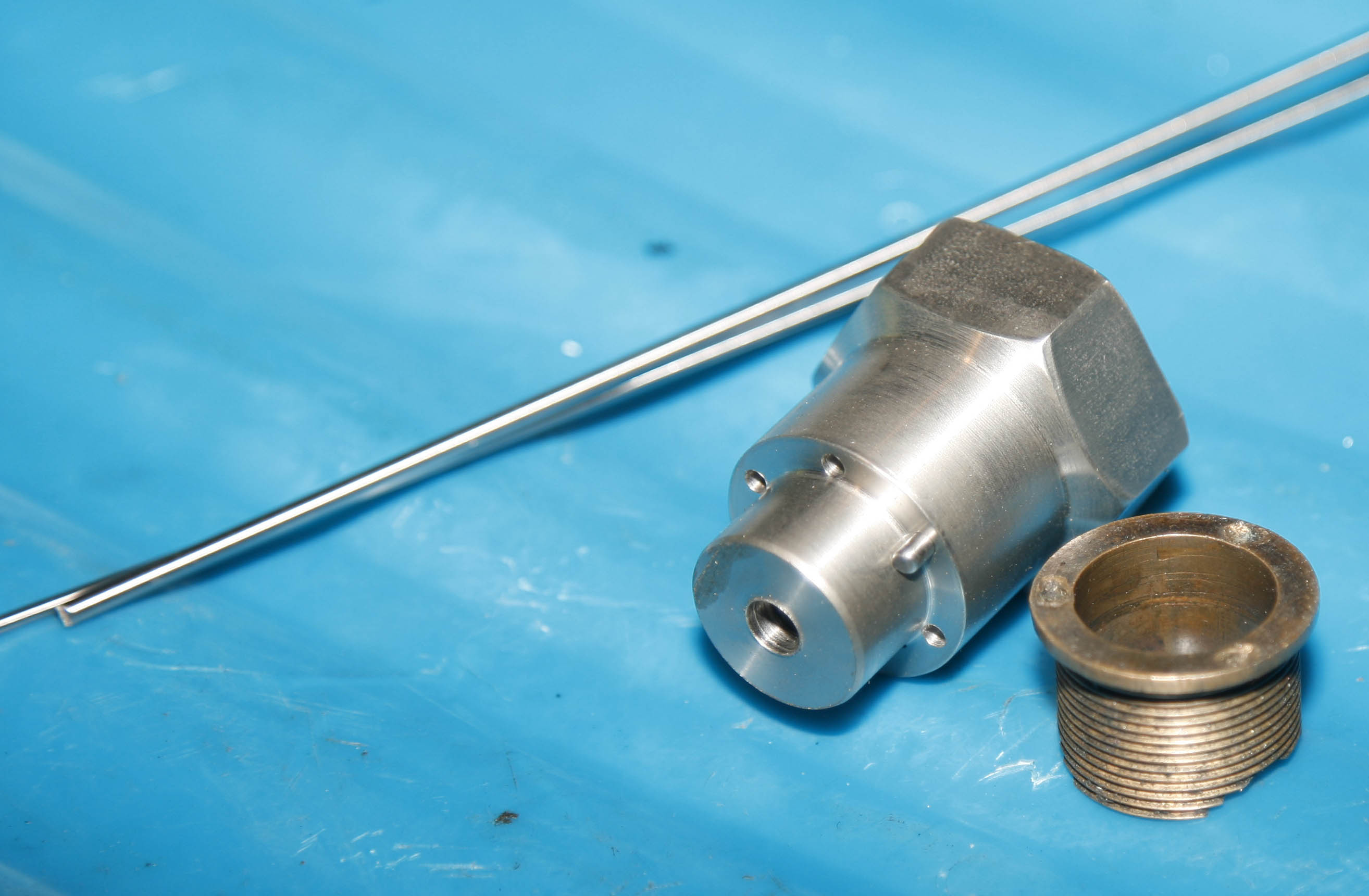
Having looked carefully at the DOHC Cambox casting - to ensure I had clearance around the cambox base area - I came up with the design of bearing removal jig you see here, with a large hex head, which would allow a big socket to be attached.
As can be seen - its lower section was a slide fit into the old bearing bore, and then there are 6 holes bored around a lip, which correspond with the 6 holes in the old bearing. Silver steel pins are then inserted into each of the holes to locate with the bearing holes. The silver steel rod is in the background. I quickly wrote a G-code program to machine this from Hex bar on my Emco CNC lathe, so boring the circumference holes would be accurate and easier to do than if I was to try it on the manual lathe or mill
Making a Pusher Bearing Removal Jig
It was not hard to figure that the probable why many years ago this cambox may have been put on a shelf - was that the cam pusher bearings were worn and needed replacement. A previous owner had started this task and sucessfully removed the other bearing, but had not been able to get the other out, and his attempts had chewed the old bearing - which I was point where he decided to give up and put the cambox in his spares cabinet.
Although not a job I was looking forward to, I knew it was likely to be the most important part of refurbishing the cambox - and making a special tool up to remove the original chewed bearing was the way to go. So a few photos and writeup on how I went about this are covered here:
And here is another picture of the finished jig - now with pins inserted and a alloy collar and lock bolt added. The most important thing about this design is that the jig can be fed into the old pusher bearing, but then with the use of the alloy collar and bolt - can be locked in place, so that the pins can not slide off the bearing when heavy spanner force is applied
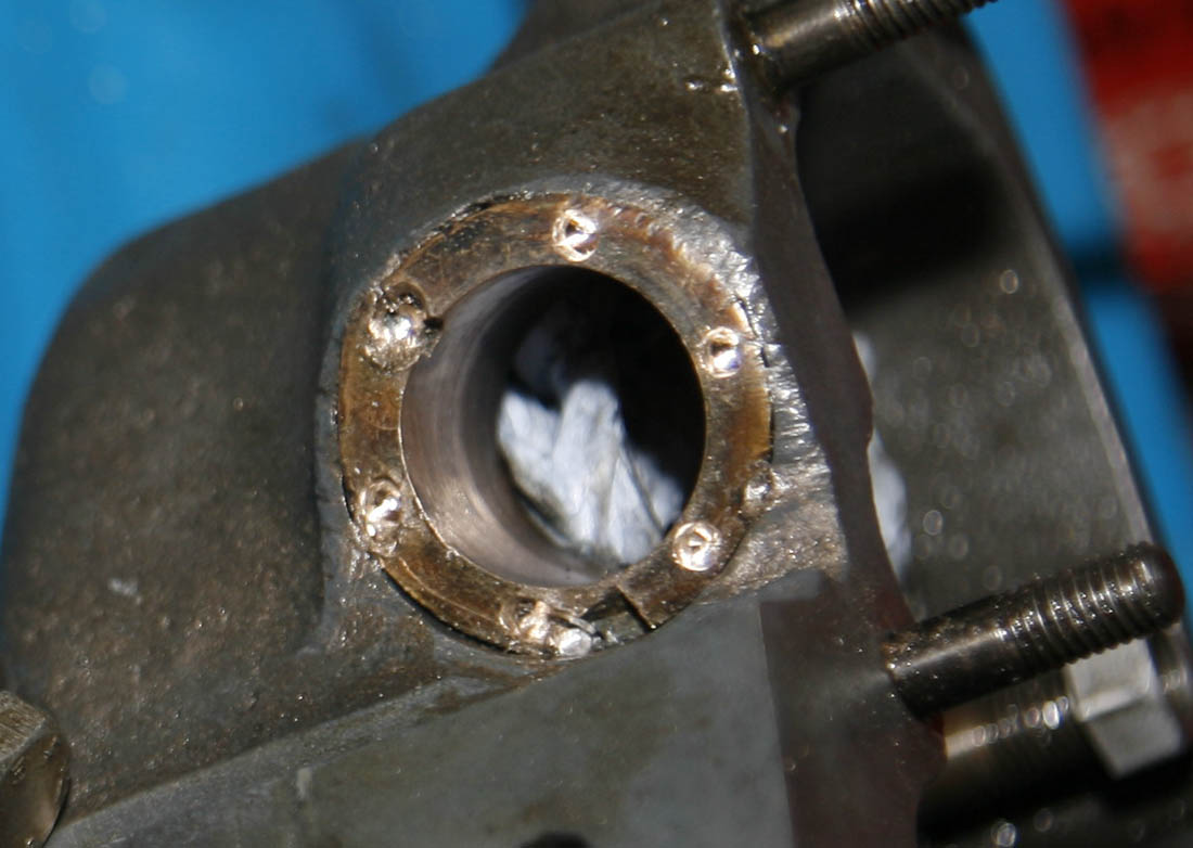
Here is a close up of the old pusher bearing to be removed. If you click on the picture above to see a larger version - you will see the old bearing looked quite knocked about in the cambox housing - which was why I was a bit nervous about how easily it would come out - the main objective being not to damage the main cambox casting in doing so,
If you look carefully you will see that I had also chased the old holes with a pilot drill to try and clean them up a bit - as they had been chewed by the previous owners attempts to remove the bearing. The original holes were quite shallow, so I knew I might just 'touch' the magnesium behind them - which would be ok, but must be very careful, so as not to risk boring through into the main cambox inner recess - which would have been a disaster! All went ok
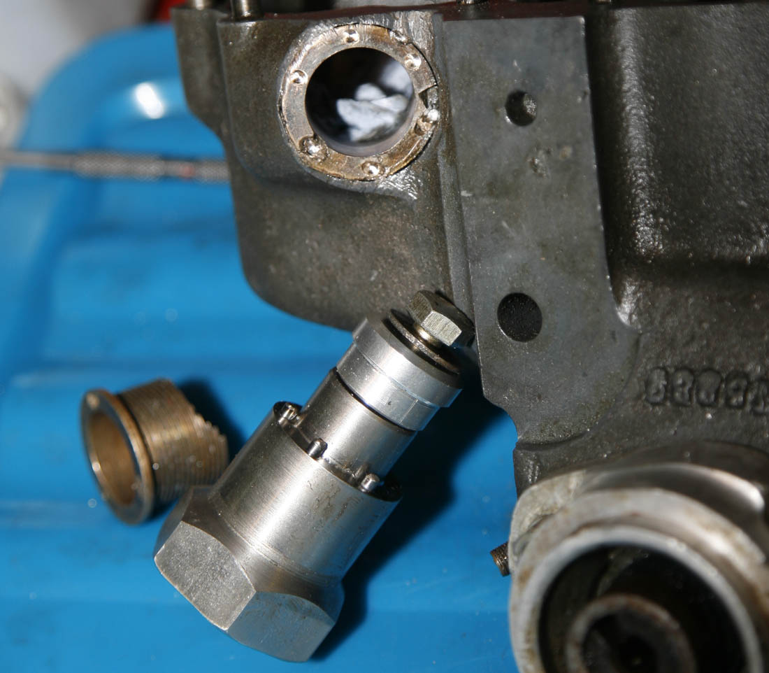
And here now is the jig fitted.
In this photo you can see why the jig had to be made so long - it had to be deep enough that the large Hex head did not foul the feet of the cambox shell. You can also see that the lip of the alloy collar is up against the base of the old bronze bearing, but due to the scollop milled in it, it is only touching for part of its circumference. However enough was making contact as to give good purchase. The lip of the collar is machined to the exact diameter of the inner bore of the thread - so it will pass through the cambox casting thread bore as the bearing is removed . . . we hope!
And now to remove the bearing . . .
Although not obviously apparent in the picture, at this point the cambox is hot, having been put to warm in our oven for 15 mins, this hopefully to expand the mag alloy enough to loosen its corroded grip on the bearing.
At this point here I have just removed the large socket to take the photo, but if you click on the picture to see a larger version - you will see that the bearing has just moved, and is slowly starting to unscrew from its recess
Wahhhayyy - Success!
Pleasingly,all the time spent making the correct removal jig paid dividends, and the actual removal of the bearing - as often the case, was a bit of an anti-climax. Having initially had to apply quite a bit of spanner pressure to 'break the seal' of many years being locked in, unscrewing and removal of the bearing after that point was straight forward and painless. I was worried the the alloy thread may 'pickup' with traces of swarf from the old milled bearing, but luckily it seemed to come out relatively smoothly.
If you look at the upper part of this photo you can seen where I had just touched the mag alloy bearing recess when I was cleaning up the holes - this was superficial though and has done no harm. Job done!
Bearing Removed - What Next?
So at this point I had a decision to make. I knew I needed new bearings to go in - so a quick check on Andy Molnar's site to confirmed he could supply them. I also knew that once new bearings had been fitted and tightened down, they would need to be milled to give them the clearance for the cams, as well as a slot for the keeping the pushers in line.
Then finally, I guessed the pusher bearings might need honing to make them a good fit with the original pushers, which I was not looking to replace.
I had not done this job myself, but had figured it should not be too difficult . . . my only concern being, my small mill was already being used for another job . . . and I was not sure what kind of tolerance was needed on the bearings to ensure the new ones would not leak.
Anyway, a quick call to Andy made the decision easy - his first question to me was 'why are you buggering about doing that yourself, when we do it all the time, and have the machines setup for doing it??? - send it up to us, and we will fit new bearings and make sure they have the correct fit'.
So, having known Andy for some time and trusting they would do a good job, I carefully wrapped it all up and sent the cambox shell and original pushers up to Molnar Manx - to let someone else do it for me!
Cambox Bevel Shaft Difficulties
So, with thie decision made to send it to Molnars' for new bearings - I asked Andy if they needed the central bevel shaft and bearings removed?, the answer being yes . . . always take all that out before fitting the new bearings, otherwise it gets in way, and swarf getting in etc etc. . . ok thought as much.
This turned out to be far more difficult than I was expecting - the DOHC shaft is a bit different to the SOHC shaft, in that it has tangs (ears) at the end of the shaft to drive the rev gearbox, meaning the special spanner I use for holding the square at the end of the shaft while I loosen the LH nut on the shaft did not fit properly. The nut as always was torqued up really hard - and I ended up catching one of the tangs and breaking it while loosening the nut - Bugger!
Then, having done this - the drive gear on the shaft refused to budge (I subsequently found - it looked like it had picked up on its shaft when the gear was last assembled, and seized.
I was struggling with this, not having any special tools for DOHC cambox's . .. but talking to Andy Molnar about it - he told me to stop faffing about with it and send it up to them, they could do that! Although my pride was a bit hurt . .. I know he was right . .. better to leave it to those who are already setup up for it.
So that was about
it for this stage of the stripdown, I duly sent the cambox shell (with central shaft still in place) in early June 2019 and a couple of weeks later it arrived back with new bronze pursher bearings fitted and machined correctly for the cam clearance. The original pushers had been re-fitted (I gather one was not standard size which meant more work than normal) and a bag was included with all the original parts removed - i.e. central shaft and gear, old bearings and a number of studs removed.
I do not normally send stuff out - thats rather the point of the hobby after all, but on this occasion it was a nice luxery to let someone else do do the legwork - and Molnar Manx are probably the best qualified - if you need any DOHC work doing, Andy's website is here: http://www.manx.co.uk/
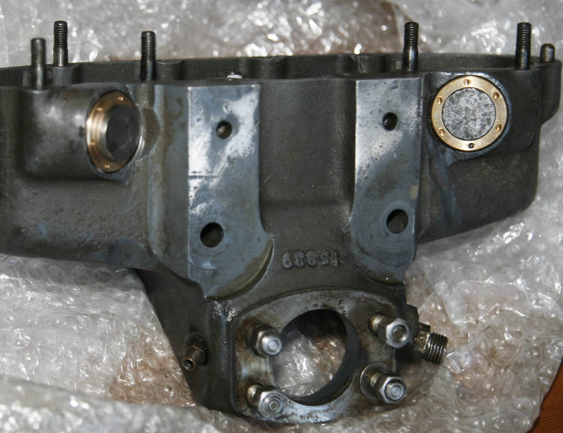
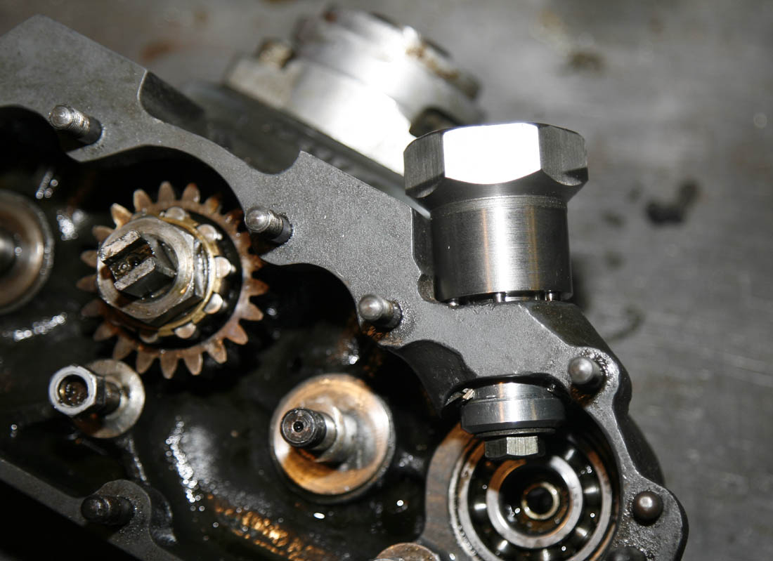
Cambox with new pusher bearings fitted when it came back from Andy at Molnar manx. They removed all blemishes off the base milled area, which is why a part of the chromating is removed - no doubt as part of mountting on their own jig for machining. Many of the studs were also removed to improve access
So having had the cambox shell posted back with new bearings, I turned my attention to looking at the central bevel shaft, cleaning up all the gears and checking the cams, deciding if to fit new bearings and then final reasembly
Here you can just see that the pusher bearing, once screwed in, has been machined flush with the flat on the side of the pusher, so as not to foul the outer cover bearing race.
An interesting feature I was not aware of with DOHC cambox shells was that the bearing housings were sleeved - as can be seen here, as the ball bearing needed to be removed to do carry out the machining
A view of the front cambox shell - which also shows a steel insert fitted in the bearing housing.
Despite appearances - which shows uneven marks on the steel bearing insert, there were no signs on the bearing of it having span in the housing, and this surface was cleaned before the bearing was fitted.
I debated for some time if or not to replace the rear and front ball bearings - as they were initially locked with old Castrol R. However, after soaking thoroughly for some days in Methylated Spirit - I checked them carefully with a magnifying glass and span them with compressed air. The tracks did not look marked and they span freely with no noticeable wear - therefore some may be suprised to know, I decided to re-fit them (at least for now). Original RHP are getting scarcer to find now (although I do supply them). . . and if these are in good condition I dont like to waste them - and they have the benefit of already being ran in and running fully free.- Here you can see them refitted
Original bearing refitted (for now), as was still in good condition with no apparent marks to bearing track.
If you look carefully at the outer track of the bearing, at approximately 3pm, you will see there is a slot ground in the outer race - this was not unusual on Manx engines (SOHC and DOHC) as it allowed the bearing cover plate to be punched against the slot to stop the bearing rotating
Interestingly, when I came to check the original Norton front bearing cover (being held in my hand in this photo) - I found the holes did not match up well with the cambox shell holes. It was grubby too, so I replaced it with our own SOHC cover screws. Like many of the DOHC cambox parts, this part looks have been carried over from SOHC to DOHC (ours fitted better though!)
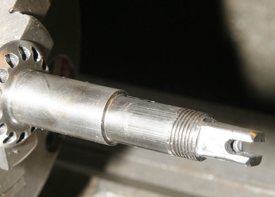
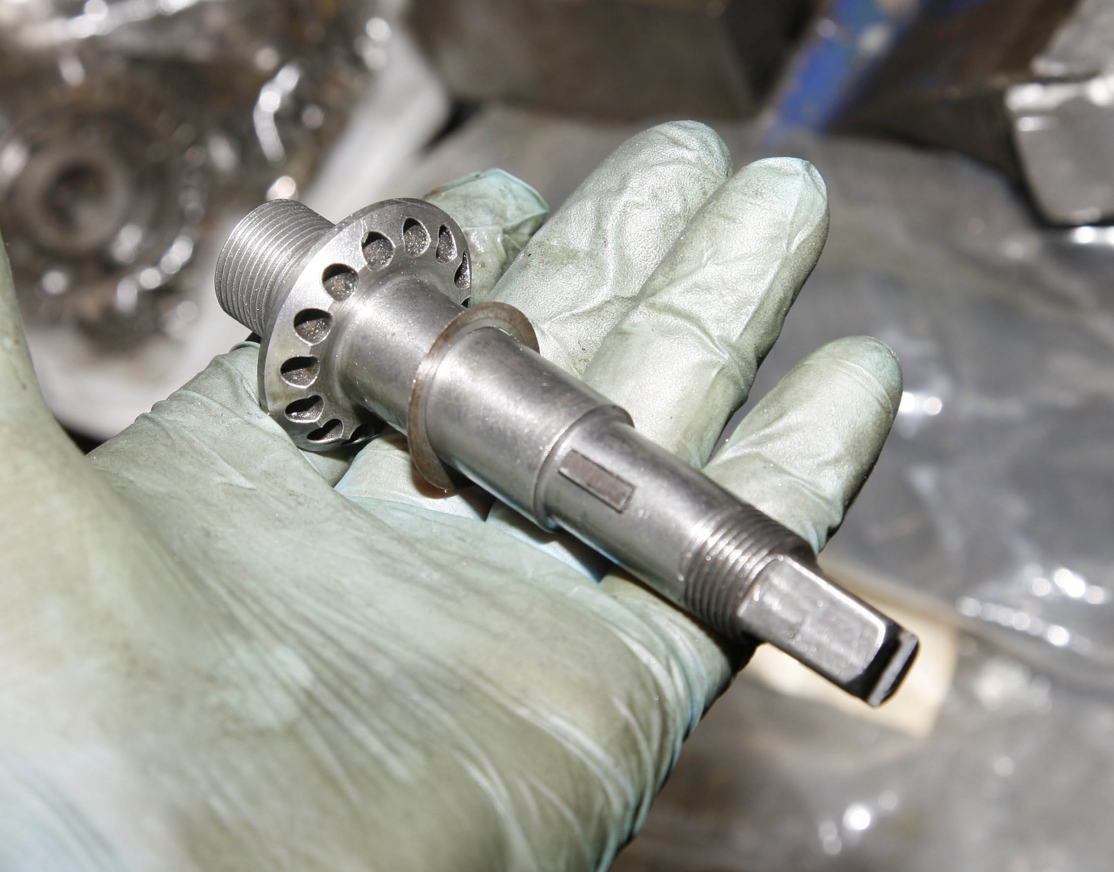
In this picture is apparent why the central gear had been so difficult to remove - you can clearly see there are striations on the area of the shaft where the gear locates, where the gear had seized to the shaft and 'smeared' the surface due to the force of removal (well done Andy for getting it off without doing any other damage to the cambox!). Although it did not look great in this photo, it actually cleaned up well with careful use of swiss files. It was also localised to the area in the photo, the reverse side was ok.
Note also in this photograph the slot at the end of the shaft for rev clock gearbox. Because one side of this had been broken off in stripdown, I had had to build up the end of the (non-hardened) shaft with weld and then mill back the slot and square - the result here looks passable
With the scored area of the shaft carefully cleaned up, the cambox drive gear was a nice firm slide fit on the shaft. Ideally I would like a light tap fit, but as the gear is locked up on the shaft with a woodruff key and torqued nut, I was happy this was still a serviceable shaft for the moment
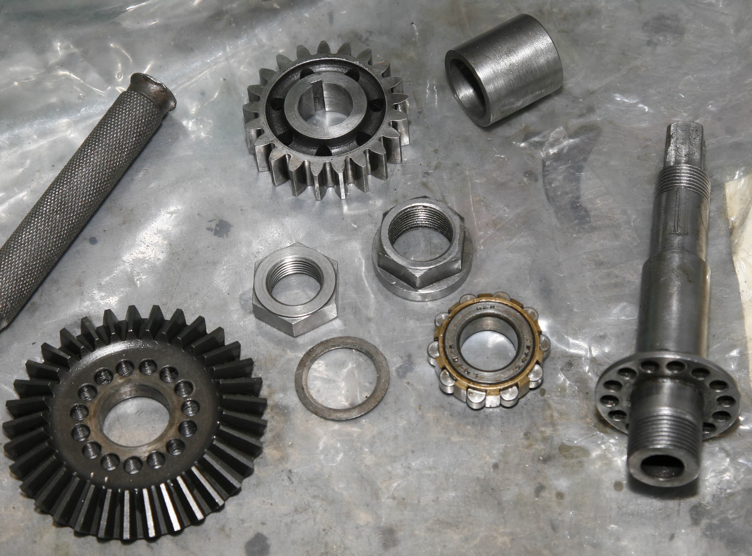
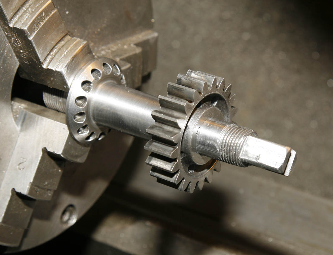
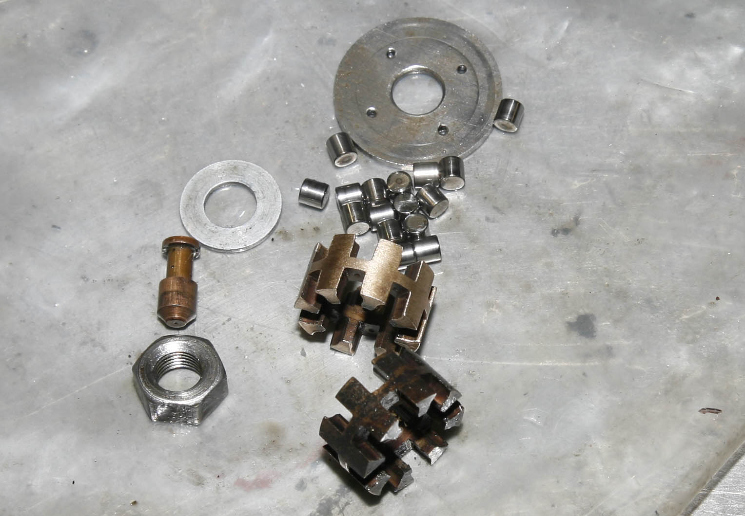
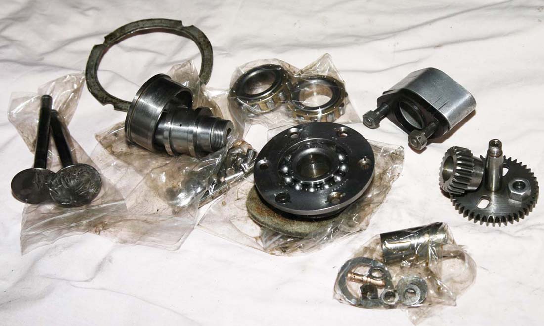
Full set of bevel shaft parts cleaned up and ready to re-assemble. The large lipped bevel nut in the centre right is original and still good condition, but the shouldered LH nut on the left is a RacingNorton item, as the original looked a bit chewed and second hand, as they often do - they have a lot of force applied to them and often spanners slip
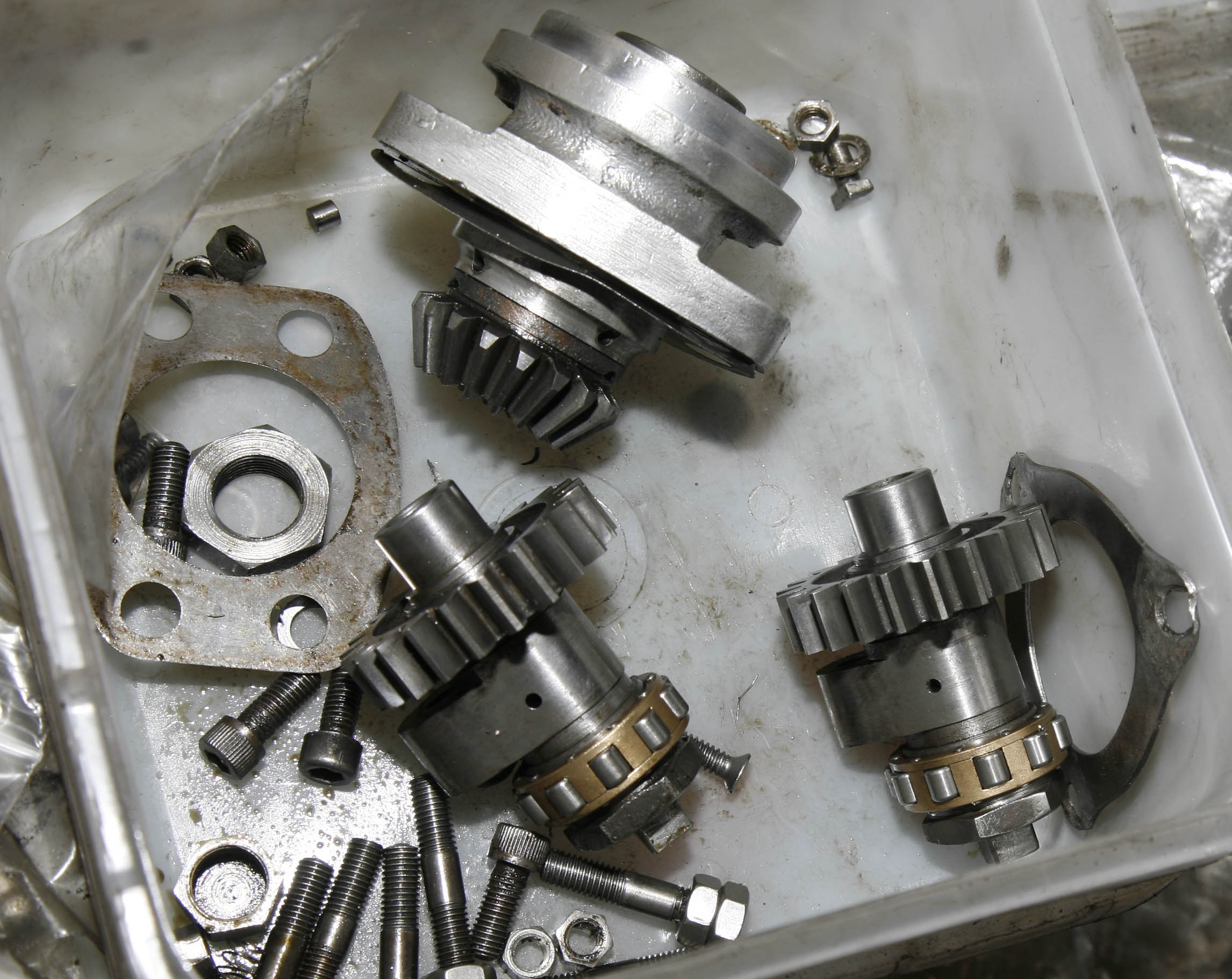
Other parts following cleanup and ready to refit. In this box are the all important cams on their respective camshafts - each a complete assembly of camshaft, cam gear wheel, cam (and locking pin), roller bearing inner race and cage, and LH locknut. Also in this picture is the cleaned up front vetical bevel housing - although more on this item later, this is a shortstroke type casting from the mid 1950's, and if I do decide to use this cambox on my Gardengate frame it will be replaced by the earlier DOHC Longstroke (magnesium) type casting
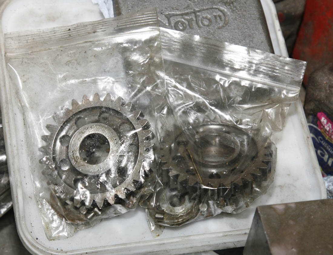
Intermediate gears are lovely pieces of engineering, with their lightened holes to save weight, and hardened/ground inner faces to utilise roller bearings - giving less resistence than plain bronze bearings. Here you can see each gear assembly is cleaned and placed in its own sealed bag so as not to mix up rollers and cages with the other
Another picture of the intermediate gear roller bearing assembly. The lower cage was as removed, still showing the old Castrol R oil buildup, while the one above is lightly stained but clean. You can also see the oil feed quill on the left of the photo - slightly different in design and shorter than the similar SOHC Manx version
Half Time Observations
At this point in the rebuild it was about 4 months since I had purchased the cambox's and had been doing the odd hour or two of work on them imbetween other RacingNorton work, or when I could get the time. But despite only working on them when I could get the opportunity - I was really enjoying working on them, everything felt like quality engineering and substantially made for the purpose in hand. Added to that, because they had stood untouched for so long, it was nice to be working on something that felt so original and unmolested.
There is no urgency for getting these finished, because it is for a future project (1950 DOHC Gardengate for this cambox - and then only if I cannot find a correct 1950 type LS cambox - but I also felt it would be no hardship to have to fit this later shortsroke example - as it was such a nice original piece of kit
Comparison of SOHC/DOHC Camshaft/Bevel Gear
DOHC cambox Bevel Shaft ready to go back into cambox. It is pretty much the same design as the SOHC item but with the extension of the square at the non bevel gear end, to provide a drive for the cambox mounted rev clock gearbox. The SOHC bike, if fitted with a rev clock would have taken the drive from the engine timing cover. Note the shim, which will fit between the bevel gear vernier shoulder and the main cambox ball bearing. It is always important to replace any shims that were replaced in stripdown - but this should not stop you from also checking the bevel gear mesh as well, and replacing/adding any necessary shims
Comparing SOHC to DOHC Cambox
While stripping this DOHC cambox, I was constantly being reminded of the lineage and similarity to the SOHC cambox. Although the DOHC cambox is definitely more advanced and sophisticated than the SOHC cambox, you can see that some parts have just evolved from earlier parts used on the SOHC cambox - the SOHC camshaft (but now called the Input Bevel Shaft on the DOHC cambox, as it did not have cams on it) and main bevel gear are both examples of this.
On first impression, both DOHC items could be mistaken for being interchangeable for SOHC items, but as shown here there are subtle differences:

while cleaning up the bevel gear and assembly, curiousity got the better of me and I decided to compare the DOHC parts to corresponding SOHC parts. In this case, in the upper part of the photograph is a genuine pre-war Manx SOHC camshaft - taken directly from the cambox of a 1938'ish SOHC Magnesium Manx engine that had also sat untouched for at least 60 years (again, it still has the coating of treacle like Castrol R, protecting it since it was last used in anger.
As can be seen, there are definite similarities but obvious differences - the two cams being mounted on this shaft being the main one, but also the lack of slotted tang at end of the square, and notice also that the SOHC bevel gear has a shoulder where it abutts the vernier adjustment lip, while the DOHC item in the lower part of the photo is almost flush with the back face of the gear
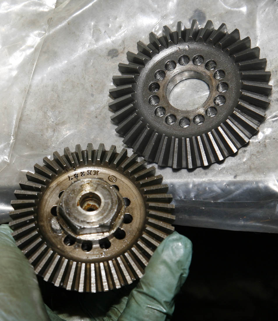
Here are the two large bevel gears next to each other for comparison - with two very noticeable differences. First of all, the DOHC item (at the top) has 15 holes for the vernier adjustment, while the SOHC item only has 12 holes. However the hole size is the same - so I assume this was done to just give a finer adjustment of the overall valve timing in relation to the crankshaft position.
Less apparent but most importantly - is that the pitch of the bevel gear is different - the DOHC teeth being coarser than the SOHC teeth - definitely not interchangeable!
Although not significant - it is interesting to note that the pre-war item has a number stamped on it and also the gear makers mark (this is actually the branding stamp of Coventry Diehead, who made engineering equipment, I have seen this stamp on many SOHC bevel gears), while the DOHC item seems only to have the twin dots of the timing marks. The surface finish also looks slightly differrent - maybe Norton's had changed gear makers or were making 'in-house' by the mid 1950's?
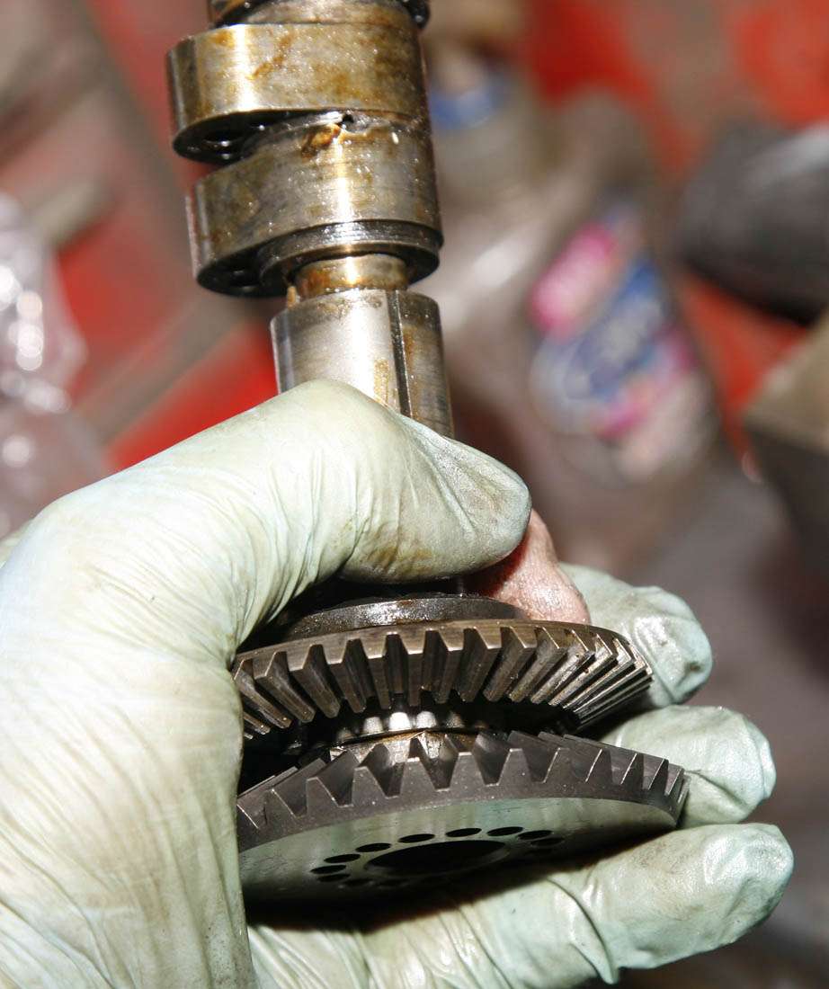
This picture gives a better view of the pitch difference between the two gears.
I am no expert on the DOHC engine, and exactly which year changes were made - but am aware there is often reference to 'coarse bevels'. I am not sure if this gear is that 'coarse bevel' type, or if there was a further change to the pitch later down the line (when they switched over to 'splined bevels', rather than using Oldham Couplings) - as the vertical bevel that came with this cambox uses), but they are definitely coarser than the SOHC teeth. I assume the main reason for doing this was to give stronger bevels - you often find the vertical bevel gears on SOHC engines either chipped or broken.
Anyway, all that said - one of the reasons this first cambox in the auction was more attractive than the other cambox was that it came fitted with the corresponding vertical bevel gear - and I dont have any spare DOHC vertical bevels of this pitch in my spares box!
Re-Tightening the LH Nut
I always cringe when I see Youtube clips of someone 'restoring' a motor vehicle using an old Adjustable spanner! - but a large King Dick adjustable with hardly any wear is an exception - the best Adjustable in the world!
But you will also see in this case, it is just to hold the camshaft in place with a special spanner I have with the correct camshaft square, and flats on its outer circumference to hold it, while a ring spanner is used under it to tighten the LH nut. It is worth noting that between this and the top photo in this section, I had checked the length of the rev clock drive against the back cover and machined the newly welded rev clock tang to length
After front bearing was re-fitted, I soldered over the BSW screws with a small blowtorch - this operation the same as with SOHC cambox. BTW - I find a blowtorch much easier than soldering iron - even biggerst soldering irons cannot get enough heat in to get a good puddle as seen here. You can also see at this point the bearing looks dry - I dont put any oil on them until soldering complete - as soldering invariably results in small spatters of solder being left in the bevel area - which can too easily get stuck in bearnig if wet with oil. Note punchmark at 9.30am, locking outer race of bearing to stop spinning
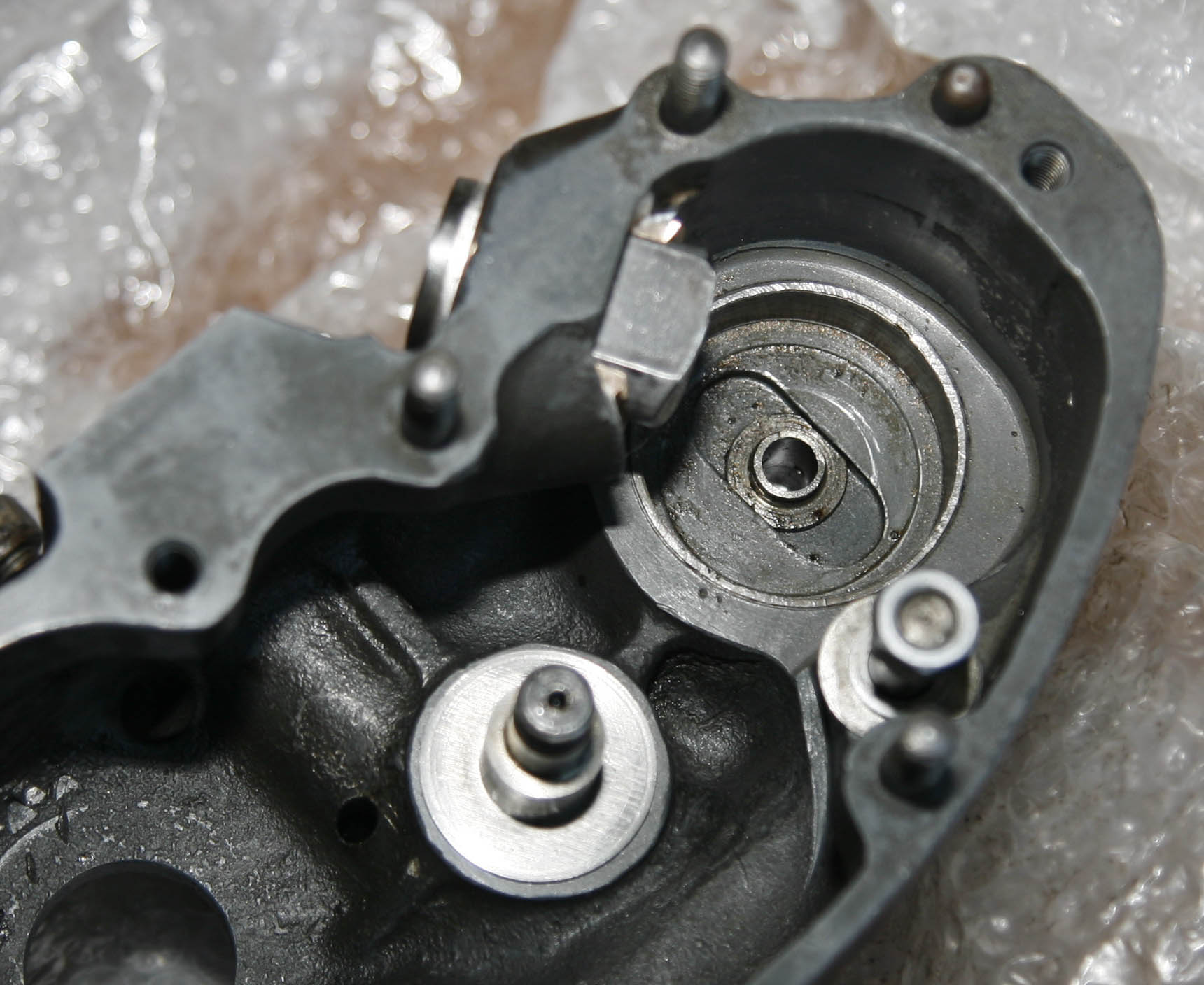
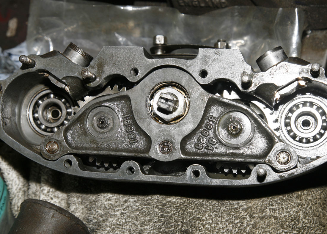
Reverting to the main cambox gear train on the opposite side - with central bevel shaft back in place (and locked up reasonably tight at this stage - it is time to reassemble the intermediate gears and their small roller bearings, before refitting side shims, which I am holding in this photo. You can see the whole assembly looks much cleaner than when I first stripped it down
You can see the camshaft bearings are also back in place in this photo, having been soaked for a week or so in light oil and span with an air line, blown out again and re-oiled. Everything assembled with mineral oil at this stage as not sure when it will next be used in anger
Here is the outrigger plate cleaned up and ready to re-fit . . . or so I thought.
It is a lovely piece or work though - note the bronze bearings pressed into the the three locating peg areas and - just like the main cambox shell, there is a steel liner where the bearings fit. And finally - the unusual oil scrolls which help circulate oil on the internediate gear bearings side shims
And this photo shows where things started to go wrong!
Re-fitting the outrigger plate turned out to be far more difficult than I imagined, as maching was accurate and tolerances were tight. The main issues was - although I could get the plate a certain distance - it proved very diffcult to get all the central bearing rollers to squeeze into the outer bearing cage without catching - this was where my inexperience with DOHC cambox's was beginning to show - it took me a while to figure out that it would have been easier to assemble the central bearing on the outrigger plate, then fit the outrigger plate in place and over the central bevel shaft, before then fitting the LH nut - my Gaff!
So here we are preparing for a second attempt - and this time you can see I have undone the LH thread bevel shaft nut and placed the central roller bearing cage and inner bearing in the outrigger plate
. .. And this time the outrigger plate went on far easier, it just needing som gentle tapping with a rawhide mallet, and almost sliding on.
Before tightenng anything else, I tightened it down by the two intermediate gear central spindles, these being the main purpose of the outrigger plate, then just checked for free movement of the gear wheels before fully tightening the outrigger dowel studs. The central roller bearing 'floats' on the outrigger outer track - the cage's final position being determined by tightening the LH nut
Final job was to refit the two cams/camshaft assemblies.
I had previously cleaned these assemblies and checked for wear of the original cams - which was minimal. I also blew out the central oil feeds (fed from the opposite side in this photograph) with an airline. However, at this stage I decided not much point in stripping down the camshaft assembly - as all looked good, and at this stage I did not know if the final purpose of this cambox would be to try and use it on my 1950 LS engine (in which case cams may need to be changed), or as a spare for my 1955 shortstroke doubleknocker - in which case these cams would stay on, looking to be 500 shortstroke cams
So here is the cambox gear train, sympathetically refurbished, ready for the rear cover to go back on. You can see both cam assemblies are installed - but not timed at this stage. As it happens, I spoke to a very knoweldgeable friend who has built many Shortstroke and Longstroke doubleknockers about cams - hoping he might be able to help out with Longstroke cams. He told me that in the past he has found Shortstroke cams work well in Longstroke cambox and recommended trying the ones fitted first!
Having finished reassembly the cambox internals, one of the last tasks was to loosely reassemble the vertical bevel housing. You can see here the original shims, which were re-fitted, so as to restore the original bevel shimming . . . but at this stage I was not concerned, because this is a later shortstroke type vertical bevel casting, and may need to be changed if the cambox is fitted to my Longstroke engine. Interestingly - this stubby Shortstroke casting was always in alloy, while the earlier LS DOHC type was in magnesium
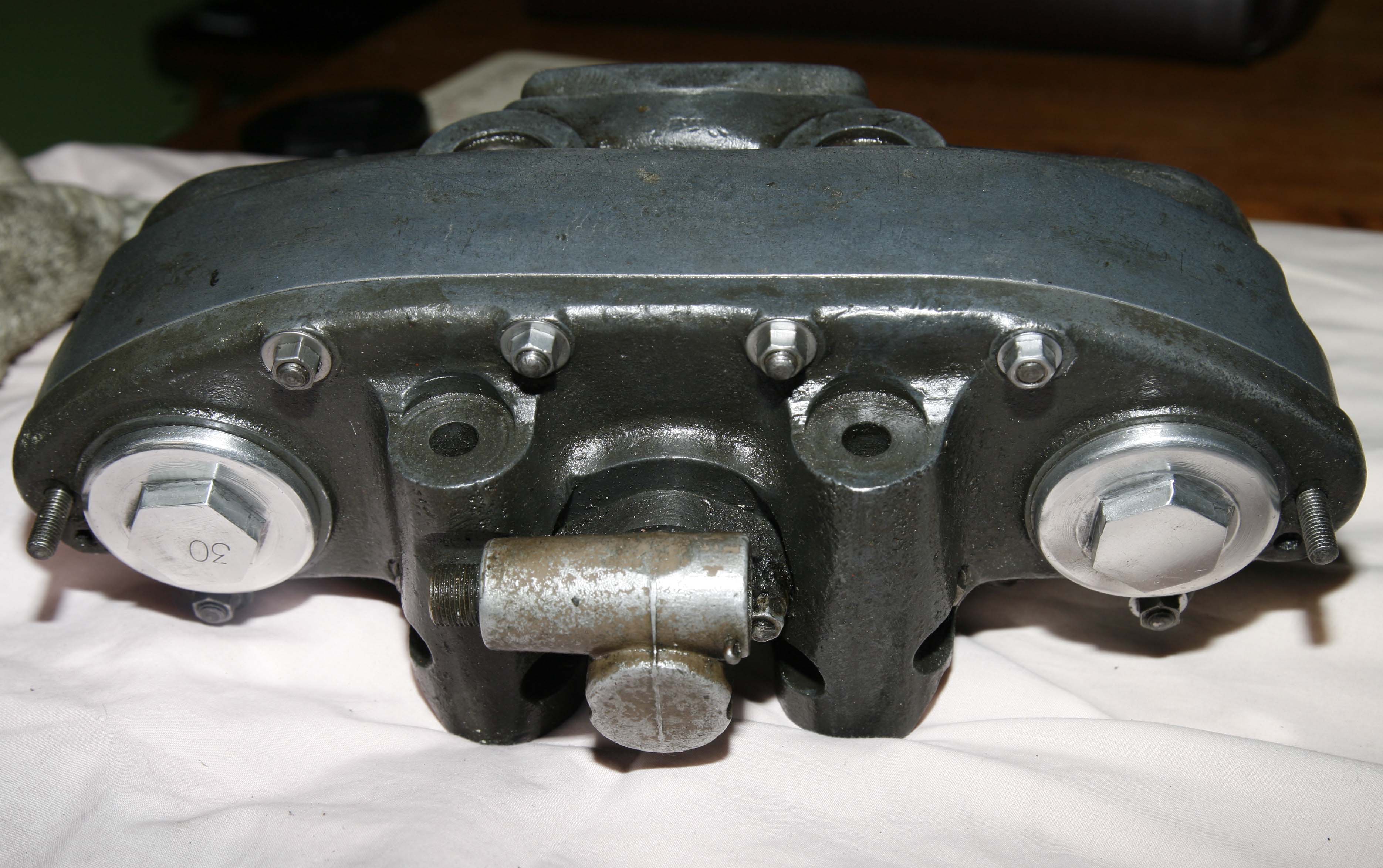
Here the bevel casting has been refitted. You can see the casting has a shallow depth and a machined outer ring - which was to fit an O ring where it then fitted into a similar recess in the shortstroke barrel, different to the longstroke DOHC type, where the barrel sat behind the vertical shaft assembly. Note here the shortstroke location pins in the base of the cambox to ensure it was always positioned correctly on the shortstroke head
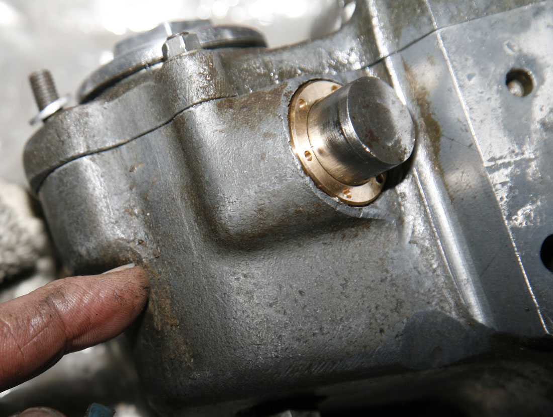
Having pretty much completed the mechanical tasks, my last efforts were directed towards trying to remove the remainder of the hard crusted Castrol R from the shell, without removing the original Chromating . .. which had a lovely bluey/grey sheen on this cambox. You can see where my finger is, it is particularly hard and crusted - almost like old Araldite!
By the way, if you look at the cam pusher, you will see it is out quite far. I had done this with both pushers so I could spin the gears easily - but is worth noting that following having new bearings fitted, they felt pretty much locked up solid! Andy informed me, that until the engine is test run they will be very tight, and it is often best to heat the cambox up if possible, before starting the engine for the first time
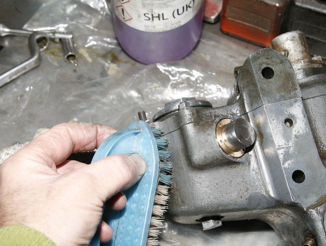
In the top of this photo you can just see a large flask of Methylated Spirit, which I have historically found to be the most effective fluid for removing old Castor oil, without reverting to some of the more dangerous specialist acids or paint thinners! I also use nylon haired brushes (or 3M scouring pads for the really stubborn areas). Even so - it is a very fine line between removing the castor oil and the underlying chromate, and I think inevitably in a couple of small areas I could not help taking both away.
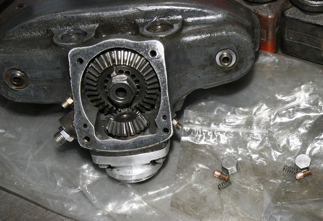
I also cleaned up and re-fitted the original cambox oil feed unions and small brass valve guide feed unions, seen here mounted back in the central bevel box casting. Likewise, sat on the plastic sheet are the two camshaft oil feed quill assemblies - including the small springs which keep the quills pushed up to the camshafts. Although I make many of these items for the SOHC cambox - I resisted the temptation to fit new items, as I wanted this cambox to be as original as possible
Since purchasing the Cambox's shown here I have also managed to obtain this very nice and original Longstroke DOHC top bevel casting, in magnesium.
It differs from the earlier SOHC top bevel casting in that the top flange is deeper, and it has additional and distinctive oil drain holes at the rear of the casting. As these were made for Manx engines only, I assume Norton's realised that the SOHC Manx top casting was not draining oil back to the bottom bevel chamber fast enough
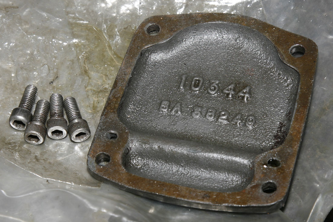
Yet another nice clean original casting was the front bevel cover, shown here with what I believe are the original hex head screws. In this photo it still has the remains of the last used gasket. Notice that -unlike the SOHC cover, this cover has an oil feed that crosses from one side to the other, to feed both camshafts.
I am not sure when Norton's first started using hex head screws on Manx's, rather than the screwdriver slot found on SOHC and roadgoing engines of this period . . . but I assume mid - late 50's. I suppose these early original ones (which are quite distinctive) are now collectable in their own right!
Final task was to cleanup the original alloy camshaft caps - which were in quite good condition - one even been stamped '30' representing a 500 (some I have seen were, while others did not seem to have any identification). They even had the original thin steel shim washers, which were cleaned and re-used.
I am not entirely sure what purpose these alloy covers had - other than to check everything looked ok and to ensure the LH camshaft nuts had not come loose - but they are pretty things. The only thing missing from the cambox as purchased was the distinctive pressed steel washer that sat over the hex of these caps and was captive against the long stud on the left of the cambox. I will probably buy a pair from Andy Molnar at some point
Last task before I packed everything away was to clean and oil the box of rusty trinkets that came with the first cambox - that being the 1960's Smiths box shown in Article 1. Having cleaned everything up and looked closely I realised there was some desirable and servicable items amongst them - which included: 'Works' style Top Hat mains conversion (my 55 Doubleknocker is ex Surtees and the engine has a similar Bill Lacey conversion), virtually new oil pump drive gears (and proper Manx with chamfered drive gear), lipped type Big End (pin and outer race look unmarked, but rollers need replacing with corrosion) and Manx inlet tract - now hard to find. Shortstroke valves on the left are totally knackered though - suspect one had touched piston!
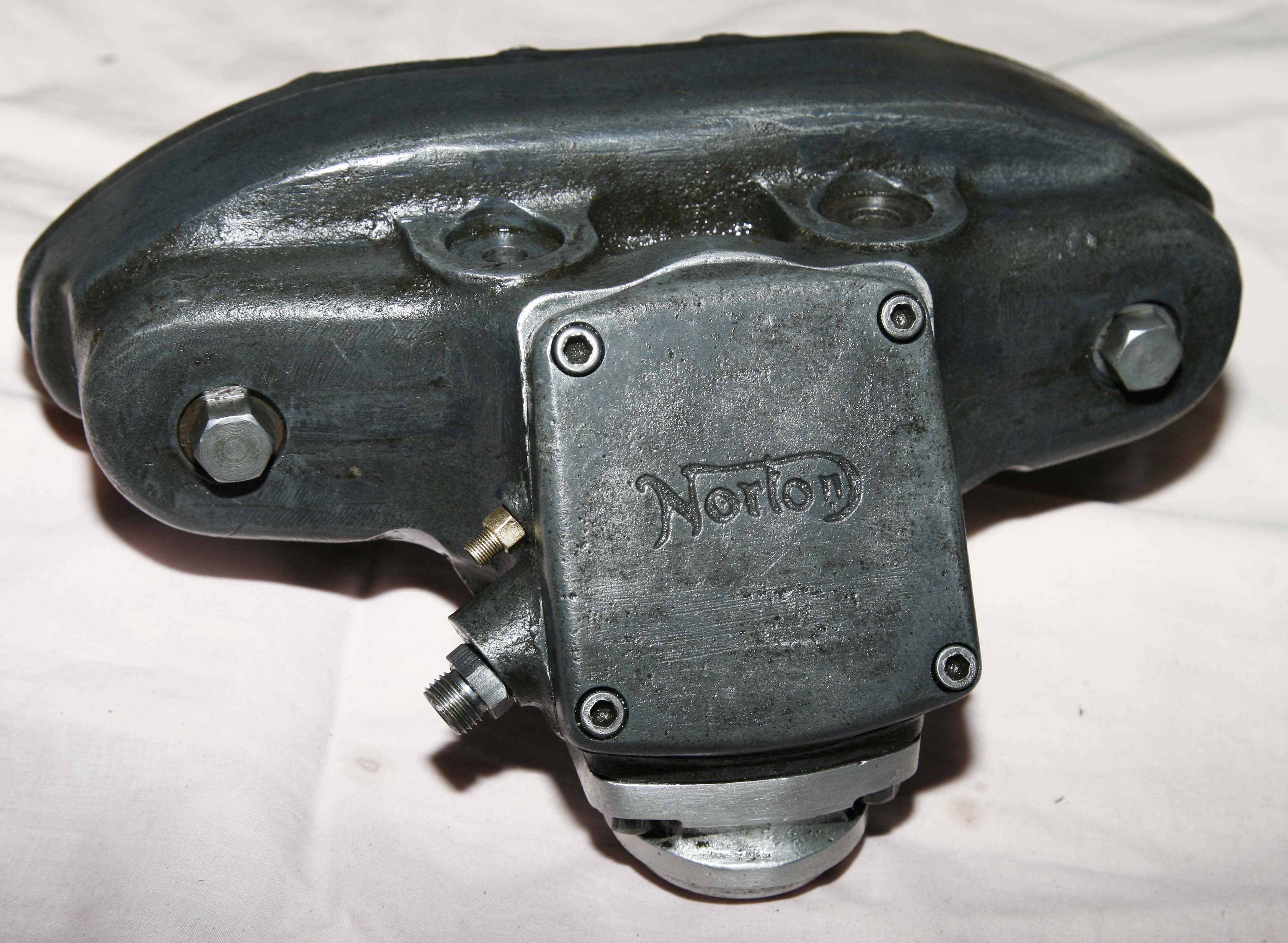
Picture of the finished job - showing the clean purposeful lines of the shortstroke DOHC cambox.
As well as being nice on the inside, this cambox still has that lovely blue hue of on an original Norton chromated cambox.
Seeing it looking like this (lightly sprayed in Duck Oil) I am very pleased I decided not to rechromate and over restore it
And this shot of the rear of the cambox confirms the same - it has a lovely patina of an original cambox in nice condition. Notice the original Norton 'reduced head' rear cover nuts and the Ochre coloured paint on the rev clock drive - I could not bring myself to try and touch that up!
Overall, very pleased how it turned out.
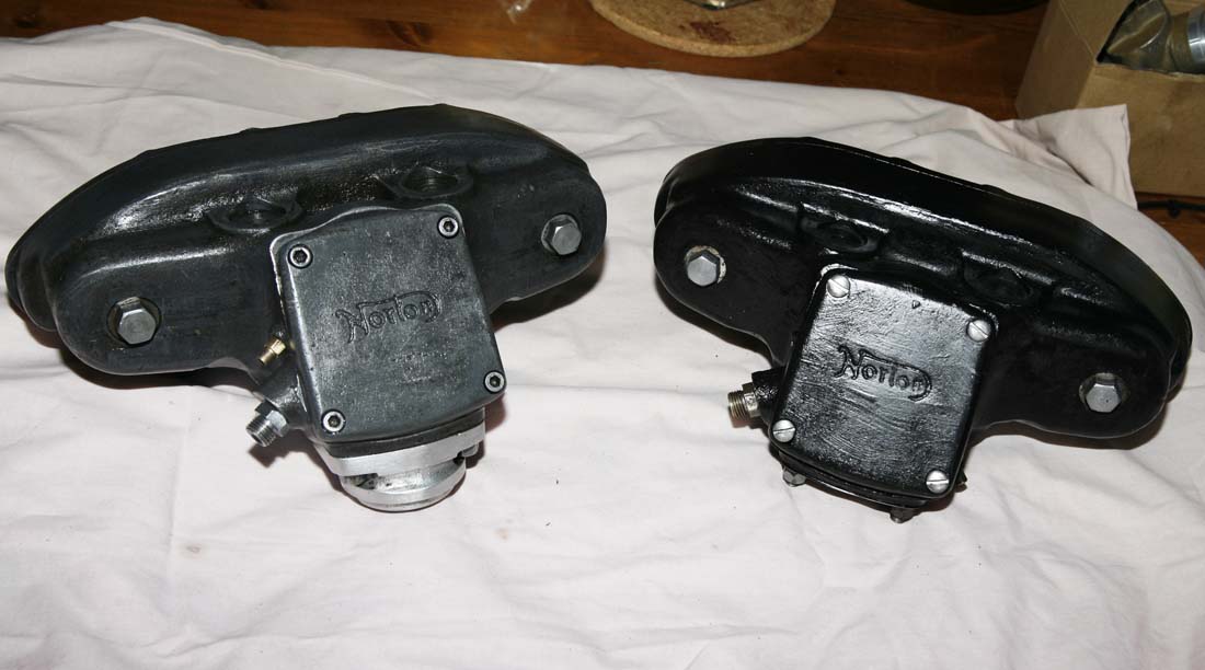
Final picture of both cambox's together just before I packed them away for the moment.
Remembering what they looked like on the day I bought them back from auction - I feel very fortunate and worth the risk, as they both turned out to be lovely original time-warp items - and so rare to get the chance to work on something so complete that has not been touched for so many years. The cambox on the right will almost certainly stay as it is - other than possibly fitting an earlier top bevel casting, if ultimately I do try to fit it to a LS DOHC engine. Cambox on the right is a long term spare and will need re-chromating at some point in the future - the black hi-temp paint on it at the moment is just a temporary job to protect it from the elements.
However, I am still looking for an earlier DOHC Longstroke cambox (or shell) if you have one for sale or swop - email me on the normal emaill address: paul.norman@racingvincent.co.uk