Assembly of Bottom Half
The term 'blueprinting' can mean different things to different people.
Personally, I dont think of it as some 'black magic', but rather it
being more about ensuring that everything is within correct tolerances
and carefully and meticously assembled. Just common sense stuff really
(being human though, while knowing this I still sometimes go and do
something stupid - like leaving the tyre lever inside the tyre!).
As far as the bottom half is concerned, most importantly this means
ensuring that the crankshaft is correctly shimmed in the crankcases,
so that the the connecting rod is exactly in the centre of the barrel
aperture when fully bolted up. By so doing, it ensures the piston runs
squarely in the bore, without the conrod placing pressure on to the
piston away from the centre line.
In the case of a camshaft Norton, this is done by shimming the crankshaft
between flywheel and timing side bearing, as it is this side that it
is positively retained to its main bearings. Having shimmed it correctly,
it is then possible to assemble the bevel gear on the other side of
the crankshaft and bolt it up with the left hand thread crankshaft nut,
so that the vertical bevel gear can be mounted in from above the bevel
chamber, and then itself correctly shimmed.
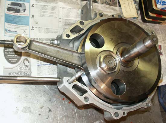
Crank placed in timing crankcase to allow correct shimming between crankshaft and timing side main bearing
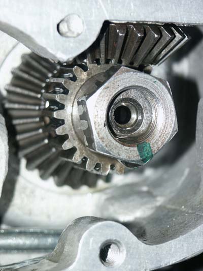
Here you can see a closeup of the bottom bevels and crankshaft oil drive gear, as well as main oilway to bigend
Again, the bevel shimming process is not rocket science, but can be a bit fiddly and relies mainly on ‘feel’ rather than any special measuring device. When correctly shimmed there should be no noticeable tight spots at any point, but with only the slightest trace of backlash. Added to this, when looking into the bevel box, it is preferable to see that the horizontal and vertical gears have full contact, rather than any overhang by one gear over the other. To get to this point, it is simply a case of obtaining a selection of shims for both the timing side mainshaft and those for the base of the lower bevel box. Then much trial and error fitting ensues, along with associated swearing, until satisfied that all is ok. Admittedly this was not a quick process and can be quite expensive on shims, but is satisfying when you feel you have it right.
Having Assembled the bottom half this far, other than ensuring everything is spotless on assembly, that is about it. I will cover the timing cover and oil pump drive gear in a later section.
As I mentioned earlier, one of the most attractive features of the engine when first offered, was that it had a very desirable bronze skulled alloy head and alloy barrel. On close inspection the head looked very nice, with very little noticeably amiss. Unfortunately, both valve seats looked slightly pocketed, which is not uncommon with these bronze heads (seats are not very hard), but other than that, pretty good. At some time in its past the exhaust port thread had obviously been damaged, as this had had a steel insert put in, but whoever did it had made a very professional job of it as it looked very neat. Actually, when looking at the head closely with Stu Rogers, a couple of months later, we noticed that a very small locating screw had been used to hold the threaded ring in place, this being very subtlety added from above, between cooling fins. We will see how this works in practice – hopefully it wont come loose under working conditions.
Exhaust Port of cylinder head showing the very neat steel exhaust thread insert. Although not visible in this photo, a small grub screw between top fins stops insert from rotating
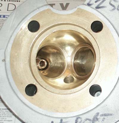
Bronze Head after porting and larger inlet/smaller exhaust valve seats cut
I talked to Stu Rogers about the pocketed valves, and also about the specification of head he uses on his own (very fast!) racing engines. He told me that his heads use a larger inlet valve than standard, with a inlet tract bored to suit. He also suggested this works best with a smaller exhaust valve (which I assume, is useful in that it means less chance of valves clashing with the larger inlet valve.
I decided that as I was going to have to have the seats looked at anyway, I would entrust the work to Stu, and have the mods he suggested done as well. What I liked about the idea of the bigger inlet valve, was that it meant I might get away with not needing a new valve seat, as the seat was going to be opened up anyway.
Anyway, a few weeks later I went up to Stu’s (sideways actually, Stu is near Wisbech and I am close to Leicester, and picked the finished job up. As well as fitting a larger inlet valve and a new exhaust valve seat, he had also opened up the inlet tract to a whopping 1.250". In the meantime, I had managed to get hold of an alloy 10TT carburettor and had machined it out to the same (very large) bore. It will be interesting to see how well this works, but I am assured by Stu that a similar arrangement in his own engines gives very satisfactory results. Final job on this was for me to reduce and shape the inlet guide (I cant help myself, I always do this) and at the same time take the opportunity to do some extra detail work on flowing the inlet port and final polishing. I think you will agree from the photographs, that if nothing else, the finished job in bronze certainly looks luvvly!
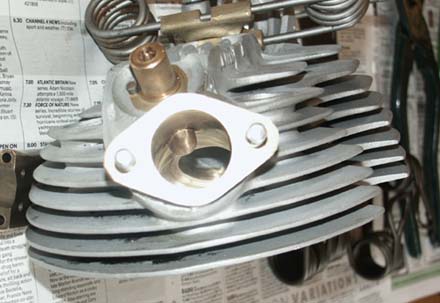
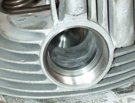
This photo shows clearly the enlarged 1 1/4" inlet tract. Note also pin next to valve guide to stop hairpin retaining casting from rotating
Assembling Head
Apart from the new valves, the head was also fitted with new valve guides
(very unusual affairs on cammy engines, as they both hold special castings
on their uppermost part, to which the hairpin valve springs locate),
new hairpin valve springs, valve spring cups and collets. All of these
parts came with the engine, and I would guess the previous owner had
spent a lot of money buying all these smaller parts.
It came as no surprise though to find that when giving the valve gear
a trial assembly, some of the parts did not fit with each other exactly.
This state of affairs with new parts used to piss me off something rotten,
but I am resigned to it now (which is normally why I trial assemble
everything first), however, it does amaze me how anyone can assemble
an engine in a similar manner to this one, without access to a lathe!
An afternoon of detail work followed, fettling all the individual parts
so they fitted exactly. Particularly, the collets did not seem to have
quite the same taper as the retainer plates they fitted into, and the
taper was fractionally different on each valve. Therefore, I spent some
considerable time ensuring the valve spring retaining plates, collets
and valves all fitted exactly, as the consequences of dropping a valve
does not bear thinking about. Lets hope I've got it right!!
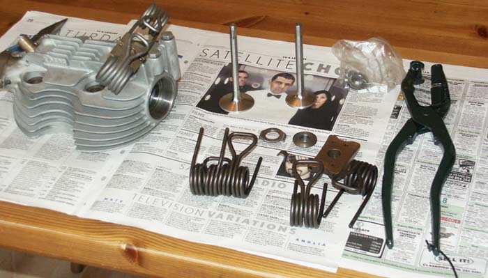
Head components ready for assembly
(hairpin on head is an old one)
The Hairpin valve springs used on cammy Nortons are one of the most distinctive parts of the engine and are synonymous to me of exotic 1930's engines. The only problem with using them (apart from the fact that they are exposed and allow Castrol R to be flung out all over the rest of the bike!) is that you cannot fit them using a standard valve spring compression tool.
This provided an interesting diversion from assembling the engine, as I decided what to do about a special tool for the job. Obviously, hairpin valve spring compressor's are not the sort of tool you can buy from Machine Mart, so the first thing to do was to try and dig out all those old line drawings seen in 1930's instruction manuals, that would at least give me a reminder what they look like.
Looking at a pair made by Stu Rogers when I was in his workshop a few days later, was also very useful to give me a good idea how they should be made. What I really needed as a starting point was an old pair of some sort of blacksmiths tongues, that I could then convert.
Having hunted my own garage to no avail, help came in the form of a pair of old tin snips in Titch's workshop which he remembered as 'never being any good . . .' (to be fair, as Titch is in his late '80's he doesn't even use his better tools quite as much these days!). Once I had the tin snips home I set to with them, first heating one of the cutting blades with an oxy-acetylene torch, so I could bend it through 90 degrees, where it could form a platform for a fabricated lip that would seat around the base of the hairpin spring. The other blade was then ground down for much of its length and I brazed to this a specially shaped tool that would press down on the top tongue of the spring. Finally, I then heated and re-formed the handle positions, so that the two handles could be easily held with one hand, once the spring was compressed. I made a little steel ring, attached by a cord, that could be placed over the handle so it could hold be left compressed, freeing both hands. Finally, having cleaned them up, I painted them a very pleasant shade of British Racing Green, just to add a bit of BS!
The finished result was surprisingly pleasing to the eye and has made fitting the springs quite a pleasure, particularly knowing they have been made specially for the job.
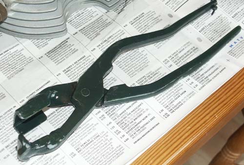
Home made Hairpin valve spring compressor's
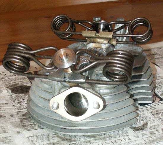
Finished cylinder head looking both pretty and purposeful
Alloy Barrel
Now, with my newly created compressor tongues and all bits fettled.
I was able to assemble relatively quickly and with no further drama.
The finished job looks nice, and with any luck, should be relatively
potent. To coin an oft used Ducati phrase - it looks in danger of capturing
small sparrows when it sucks in.
After the complexity of the head l was hoping the barrel would be relatively
simple, no such luck!
Although relinered and looking in very good nick, there was just one
problem, the top of the inner spigot did not sit high enough to touch
the mating face of the head. This could have been for a couple of reasons,
but favorite is that either the new liner or the barrel itself is not
from the same period as the head, maybe a post war item. I looked at
all the various ways that I could get round the problem but short of
skimming one of the outerfaces, none of them were ideal. Even this was
not a good option because the barrel itself looked to already had as
much skimmed as acceptable.
For the moment I have gone for a get round which, although I am not
comfortable about from an engineering perspective, is at least worth
a try. I have made a spacer ring from a similar material to the liner
and with the exact dimensions of the missing area of metal. This includes
adding a couple of thou to its depth, so that when the head is mated
with the barrel it touches on the inner face first, but tightening the
holdoing down bolts then causes the outer faces to touch (Top Hat effect).
Having machined a suitable ring, I then deliberated if it would be best
to let it 'float' loose, or if it should be fixed, either to the head
or barrel. In the end I decided to fix it to the barrel, using a super
strength Loctite industrial adhesive, used for extreme strength applicatons.
I'm not sure how well this adhesive will stand up to the heat, but I
reasoned that its not the end of the world if it doesent work well,
as it is only there to stop the ring rotating and to make the stripdown
process easier. As I said, it will be interesting to see how this works.
Postscript Jan 2006 - Having now ran the engine and it having successfully
competed in its first sprint, I am pleased to report that this seems
to be bearing up well, with no signs of head gasket seepage at all.
I have not had to remove the head for inspection yet, but will report
back findings when I do.
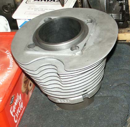
Desirable alloy barrel came re-linered and freshly bored to +0.030"

Return To Top of Page