Racing
Inter Restoration - Part 4: Timing Chest and Oil Supply
(August 2005-September 2005)
This section is really just a quick recap of what I have already covered in section 2, which describes the bottom end rebuild. I was fortunate with this particular engine, as when bought it was in very good condition overall and did not require much remedial work to the bottom end. In fact as far as the timing case was concerned there was almost nothing to do, other than giving it a final clean and preparing parts for final assembly.
The oil pump had already being fitted and although not feeling 100% comfortable about not stripping it down myself (a bad habit of distrust that seems to be a failing of mine, not just with motorcycles but in most aspects of life!), on this occasion I took the decision to leave it alone, as to strip it would mean heating up the crankcases, potentially loosening the main bearing to remove. (postscript – having ran the engine now for some time the oil pump seems fine, but on the current Manx engine I am building the pump has come out and will be the topic of a future article).
Just to explain though, in case you are not familiar with the oil pump used in SOHC Norton’s, it consists of 3 pairs of gears, all set in a cylindrical pump body, made of a zinc like monkey metal called Mazac, similar to that used by Amal road based carburettors such as the monobloc. Each of the 3 pairs of gears form a ‘slice’ of the pump cylinder and are a separate individual pump in their own right.
As with the ES2/16H based road going models (which has very similar gears although in a different shaped body), the first set of gears is to provide a feed to the Big End. The second set of gears provides a scavenge from the sump back into the oil tank (i.e. a dry sump engine). However, where different from the more humble cooking models, the SOHC oil pump provides a third set of gears, providing a second scavenge to feed back oil that has drained into the bottom of the timing chest from the cambox.
Not sure how well this pump compares to the pumps of other motorcycle engines, but arguably it must have worked pretty well, as it remained without change until the end of the DOHC Manx’s life in 1962, quite an achievement when you think about it! I am told though it was copied originally from the similar Velocette design by Carroll.
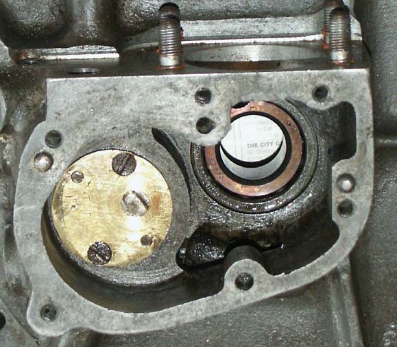
This shot clearly shows the timing case aperture of a SOHC Noton (in this case a magnesium Manx crankcase). The oil pump sunk in to its cavity can be clearly seen
What is a little bit difficult about working on this pump, when compared to its OHV and SV brother’s, is that it is shrunk into the crankcases, rather than being just bolted on, as with the road going version. This makes the removal of the pump - although not tremendously difficult (my wife is very used to coming home and finding crankcases in her oven), not something that should be undertaken lightly. Not only do you have to ensure the pump goes back in exactly the same place (little threaded ¼ rods to guide it in, about 2-3 inches in length are best), but also, heating the crankcases can loosen off the main bearing, so this needs to be considered as well.
Oh, by the way, one other point that is worth considering if you are
buying a new or second hand pump for one of these engines is to consider
the interference fit. I was told this by an experienced friend (who
is always on the look out for cammy engine bits), that the tolerance
on these pumps can vary quite considerably from one pump to another.
Certainly he says he never fits a new pump into an engine unless he
has checked it first and sometimes finds one where – if fitted,
would have caused a problem due to being considerably oversize.
Stu Rogers (who kindly proof read this article) tells me that the interference
fit on the pump should only be 0.5 to 1 thou (I had guessed –
incorrectly, that it would be 2 thou), and that Norton offered the larger
pump bodies as a reclaim alternative, which is strange to think that
they would get worn?
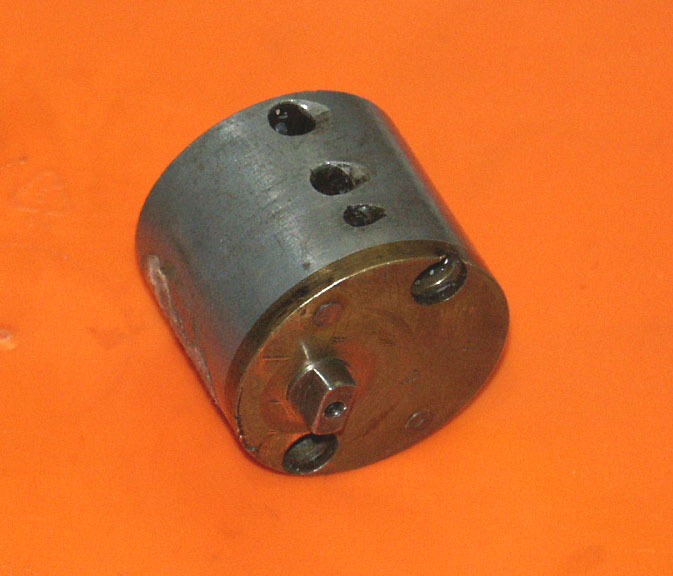
The cylindrical Norton oil pump fitted to all SOHC and DOHC engines. The three inlets on the top each represent a seperate pump element
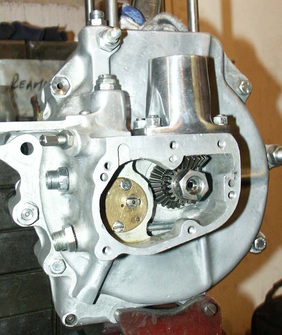
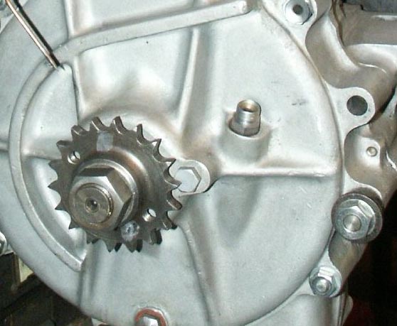
This shows my Inter engine with oil pump in situ and bevel gears assembled. It also gives a good viewpoint of the various oil fittings described in this article
When discussing the oil pump, Stu was keen to point out that a job well worth undertaking, is to machine out the base of the oil pump crankcase housing, if it has become scored by the scavenge pump gears (the pump body not having a rear face, these gears act directly against the crankcase wall). Stu suggests that machining it out a minimum of 15 thou then fitting a similar sized brass shim to reclaim the depth is the way to go.
Anyway, with the oil pump already fitted, all that remained to do in this area was to ensure that it span freely and that all of the oilways were absolutely clear and had not picked up any debris on its journey to my workshop.
More On the SOHC Oil System
As well as the oil pump, there are a few other components associated
with the oil circulation that are worth a mention. The majority of these
parts bolt on to the timing side crankcase, so I will touch on them
here:
- There is a rudimentary filter fitted to the bottom
of the timing case, which is designed to collect the oil draining into
the timing cavity from above. It is of unusual construction, consisting
of a hex head, with thread behind it, two inches in length of thinwalled
hollow tube of approx ¼” in diameter, which has very fine
slots along its length. The idea is anything larger than the smallest
particles won’t get past the slits. I believe this component is
machined from solid, certainly the replacement one from Stu Rogers for
one of my other engines looks to have been made in this way, and nicely
done too.
By the way, the very earliest cammy engines were not fitted with these
filters, instead having a rudimentary gauze filter over the timing cover
pump scavenge hole orifice. Therefore, if you have an engine without
one it is pre 1934.
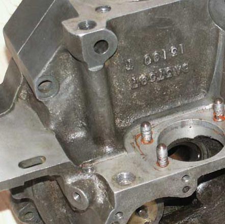
Here we see the oil filter fitted into the base of the timing case
This is the oil filter thats is fitted to the base of the timing case. Note the fine slits, designed to trap fragments of debris
As with the timing case filter described above, this pressure indicator was not fitted to the very first SOHC engines, however it was fitted from (I think!) 1931 onwards. If you happen to have a set of these very early crankcases without either filter or telltale and would like to sell them, then please let me know as I have a friend who would dearly like to find a set for one of his bikes.
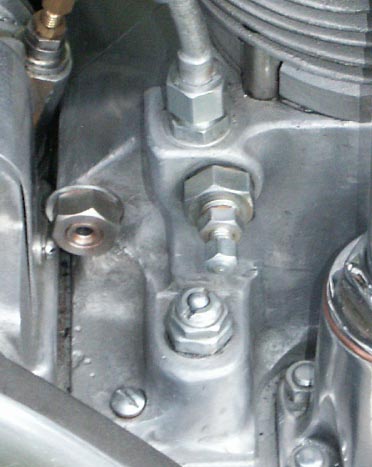
In this photo you can see both the Oil Pressure Indicator and feed bolt to the rear of the cylinder. When the engine is running the central part of the indicator raises approx 3/8 inch
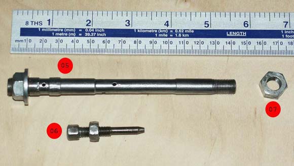
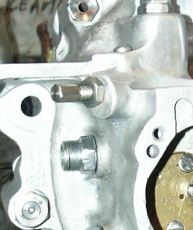
Another shot of the Rear Cylinder Feed Bolt assembly. You can clearly see the oil feed holes in this shot. The bolt should be a tight fit in the crankicase
Oil Pressure Relief Valve Adjuster, which is not immediately visible once the timing case is fitted
The cambox oil pressure is best adjusted using a pressure gauge attached to the cambox feed pipe. This valve should then be adjusted to give about 10-12 psi when cold, or about 8 psi when warm (the important figure). Tightening the adjuster (clockwise rotation) will increase the pressure.
Stu Rogers recommends it being a good idea to lockwire this adjuster if road racing, as the consequences of it unwinding is to loose the contents of the oiltank!
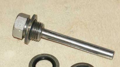
- Rear Top Engine Bolt/Flow Adjuster: Finally, the SOHC engine is fitted with an unusual engine bolt that is drilled through it’s centre and has two further cross drillings along its length, that correspond to holes in the crankcase and barrel, so oil can be fed to the rear of the barrel. The flow of this oil is controlled by another (tapered) adjuster and locknut that screws into the centre of the bolt from the timing side. The ideal setting for this adjuster is said to be when you can visibly see a puff of smoke from the exhaust on the overrun, which is about 0.5 – 0.75 of a turn out from fully home. Again I set this as the initial setting, which as a postscript did turn out to be very close, for when I first ran the engine, I only had to make a very minor adjustment (However, I have not stripped the engine down yet, so will hold off a final verdict until then).
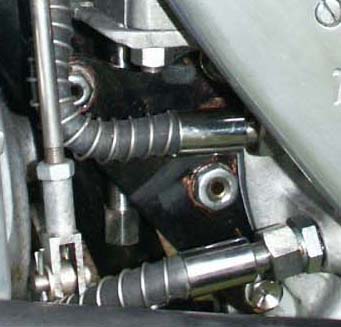
Looking at the rear of the crankcase, this photo shows the oil unions and original style 'wired' oil pipes
These unions are different to those fitted to the more humble OHV/SV engines of the period, in that they are made to take a larger diameter oil pipe union than pushrod and sidevalve engines. The original oil pipes are also very distinctive, and in my opinion an absolute ‘must’ for any proper Inter restoration. The inner pipe is a larger bore black pipe, but then wrapped around it is a spring like outer protector, with large (aluminium) ferrules at each end. If you have seen these pipes yourself, I am sure you will agree with me they are very distinctive and to me archetypal of the design features of racing machines of the 1930’s.
I have kept an eye out for originals of these pipes for many years, but not surprisingly they are extremely rare now, and often in poor condition even if they can be found (I did recently pick some up from a well known sponsor of many years and was extremely grateful).
However, help is at hand as Stu Rogers now sells all the unions for these engines in stainless steel as well as made up sets of oil pipes, to the original pattern, ready to fit. They are not cheap, but having tried to make up one of the pipes myself, using the individual components – and failing dismally!, I would fully endorse those that Stu produces and would rather just buy them ‘off the shelve’.
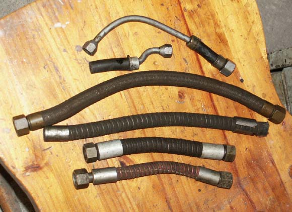
A selection of original(ish) oil pipes. 2nd from bottom is a genuine SOHC feed pipe, while below it is a similar pipe with red rubber. Not sure what the largest pipe is from but has braided steel sheath. Top two are original OHV oilpipe fittings from similar period for comparison
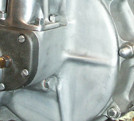
Drive side International crankcase, showing engine breather in the traditional position of most Norton singles. Note also engine drain plug at base of crankcase, normally blanked on Post-war Inters
By the way, on the subject of breathers, this is one of the differences between International crankcases and SOHC Manx (magnesium) crankcases of the same period.
Providing an interesting comparison with the International crankcases, these SOHC Manx cases are identified by the lack of oil pressure indicator. Instead, the hole closest the camera holds a breather similar to that fitted on the drive side crankcase

Return To Top of Page