Racing Inter Restoration - Part 7: Setting the Vertical Coupling Assembly
In this section I will cover the last main area of assembly for the
SOHC engine, the vertical shaft and oldham coupling assembly.
Although not overly complex, assembly can be quite fiddly, and getting
it wrong can result in excess wear or damage to the bevel gears, which
are now getting very difficult to obtain.
When Arthur Carroll designed his new camshaft engine for Norton in 1929-30, the most visible difference from the earlier Walter Moore CS1 engine design was in the area of the vertical shaft design, and in the utilization of two new aluminum castings, one top and one bottom, that were designed primarily to house the vertical bevel gears, and allow accurate and captive location of the Oldham couplings, which in turn transfer drive from lower to top bevels via a vertical shaft between both.
These castings have a wide locating flange (approx 2 inches in diameter, by quarter of an inch deep) that allow them to positively locate into either the crankcase bevel chamber (for the lower) or the cambox bevel chamber (for the top), ensuring there is no possibility of lateral movement, which could result in the bevel gears being misaligned during assembly. The advantage of such a wide flange is that there is less chance of wear developing over the years, due to constant strip-down and reassembly. Although difficult to put into words, I always feel a strange sense of satisfaction when assembling these castings into either the crankcase or cambox, which I can only describe as feeling ‘engineeringly right’!
These bevel castings are secured into the parent castings by the use of four 5/16” studs, that pass through each corner of the casting, and then use special reduced head nuts to tighten down, as there is not enough room to allow normal width nuts (as a blatent advertising plug – I supply both the studs and the correct reduced nuts in stainless steel!).
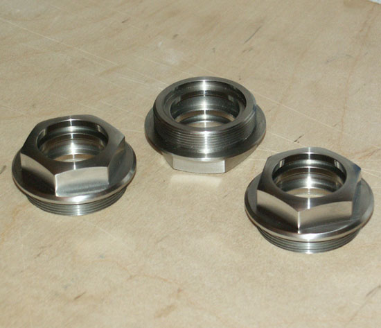
Alumininium Bottom Bevel Casting.
You can just make out the bottom Phoshor Bronze bearing in this shot,
and also the thread at the top to take the large gland nut.
Although identical to the original fitted to the Racing Inter engine,
this one is actually one of my reproduction items - most original
ones have worn threads and look much more distressed!
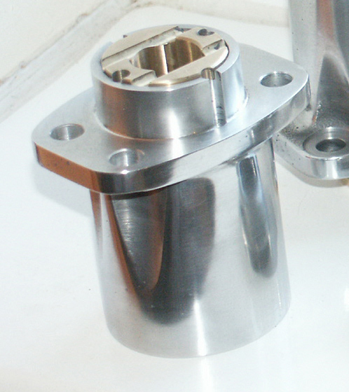
And this is the similar top casting (again - one of my new components - go to my SOHC catalog if you want to purchase one). Note in this shot the cross grooving in the bearing, to help drain oil from the cambox
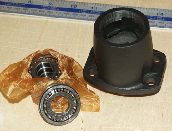
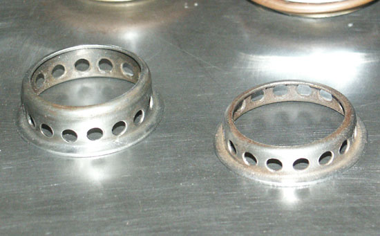
Here is the twin row ball bearing originally fitted to the bevel castings (in this case a magnesium unit). Interestingly RHP always used to supply them in ' tube' format, wrapped in grease paper, as shown here. Now obsolete and virually unobtainable
As well as the plain bearings, the castings also hold a second bearing this being a slim 2 row caged ball bearing. These twin row bearings do not actually support the bevel gears themselves, but act as a locator for the Oldham couplings that slide into the slotted end of the bevel gears.
A lot has been said about these bearings, much of it blasphemous!, due in main to the tendency for the bearings to shed its tiny balls as soon as there is any wear in the phosphor bronze cage, the result being that the balls can drop down into the crankcase bevel chamber where they can catch in the bottom bevel gear and result in broken teeth. The tongue in cheek view of my old friend Titch Allen (who was around when these engines were current technology) was that Norton’s considered this one ot their best design features, as it kept their maintenance depots in constant activity!
I think the idea of these bearings was that they were self centering, so they would have some lateral movement when you were removing the cambox from the engine, without having to remove the whole engine from the frame. They allow you to tip the cambox forward slightly, so it can be angled out from under the top frame tube. The problem is, that although the bearings allowed the cambox and vertical shaft to be moved ‘off centre’ so to speak, if there was any wear at all in the bronze cage, out would pop a ball or two and drop into the bottom bevel chamber.
These bearings have been obsolete for many years and trying to find them is becoming increasingly difficult. Because of this most people replace them with a rigid single row ball bearing alternative. Although these bearings do not lend themselves quite as easily to removing the cambox when the engine is in the frame, they are much easier to find, do not loose balls like the other bearing and I am told work just as well.
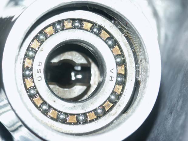
And here is the same bearing fitted, with bevel gear slot visible. It should be noted that it is easier to fit the bevel gear before fitting the bearing, as a collar is pressed over the shaft of the gear, which is easier to fit before the bearing is put in place
Next component in the bevel drive train is the Oldham Couplings themselves. These are tanged connectors in various lengths and they are designed so that the tangs on either end are 90 degrees apart from each other. They were originally supplied in various lengths, to take account of various compression ratios being used, the difference in length always being accounted for by the centre section width, the tangs themselves are always of a standard size. If you happen to come across an Oldham coupling with much shorter tangs (I have a couple of these in my collection), then chances are they are from the later DOHC racing engine and are not compatible with the SOHC engine.
By the way, the bottom Oldham coupling should always be of 3/16” thickness, only the top coupling can be varied in length, of which more in the next section. Also, it is very important that they are a good slide fit into the bevel gears and vertical shaft, without any traces of wear or looseness which may result in eventual failure. Quite often you will find that one end is slightly tighter than the other (and I don’t think it being tight does any harm), but there should be no perceivable play on the other side of the tang at all. I guess the reason they go like this is that inevitably they do wear in, and the wear develops in the direction of rotation.
Footnote Feb 2008: These Oldham couplings are not easy to find at all, and particularly in the longer lengths the chances of finding them at autojumbles is remote. I have been asked by lots of people if I can supply them? I am currently testing a test set in my own racing engine, and if all goes well I hope to be able to offer various sizes later in the year. The original type were normally machined then hardened afterwards. I am experimenting with making them in a much harder (heat treated steel), which means they should not need further hardening after machining.
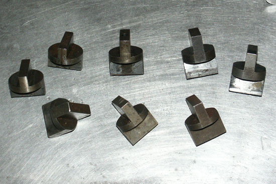
A variety of original Oldham Couplings, of various thicknesses (press on the thumbnail to see a close up).
Note that the pair in the top left corner have shorter tangs and are from a DOHC engine
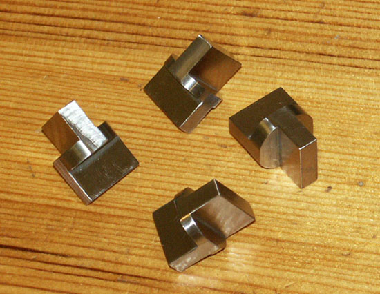
And here are a small batch of new Oldham Couplings I have had made, which were tested in the Racing Inter in Spring 2008 . I hope to have some available for sale late in 2008
Vertical Shaft
This is the final component in the drive train. It is normally of a
standard length (500 and 350) and has a lip on one end. This is the
bottom fitting, and is very important that it is assembled correctly,
as the lip rests against the lower bevel ball bearing cage and stops
the shaft dropping thru and applying positive pressure against the bottom
bevel gear. Obviously, they were supplied in different lengths dependent
on the capacity of the engine and I even have one of the very rare longer
596cc items in my collection. As I mention above, just like the Oldham
coupling to the bevel gears, it is very important that lower Oldham
coupling does not show any signs of slackness when it engages with the
vertical coupling, as this will lead to premature failure. Luckily in
all the examples I have seen, this shaft seems to show very little signs
of wear and is generally a very robust item.
Note also that the vertical shaft is hollow. If truthful I am not entirely sure if the original intention of this was to a) aid oil passage, b) aid breathing or c) make the coupling a stronger unit. Maybe someone out there knows more than I and can let me know so I can update this section?
In this photo we have the vertical shaft on the left side. You can clearly see the lip on the bottom of the shaft, where it 'sits' on the bearing
Assembling the Vertical
Bevel Gear Assembly
There is a simple and logical order of assembly for the vertical assembly,
to ensure the bevel gear backlash is correctly set, which can be summarized
as follows:
1. Correctly shim the end float of the crankshaft in the crankcases
(see Section 2)
2. Assemble bottom vertical bevel gear in the casting and then trial
fit this into the timing case.
3. Shim both behind the crankshaft horizontal bevel gear and under the
lower vertical bevel casting, until lower backlash is correct and gears
are giving best possible mesh contact area (see Section 2)
4. Repeat procedure for the upper bevel gear casting and cambox (see
section 6)
Note : at this point, both sets of bevel gears should independently have their backlash set correctly. If after final assembly of the engine this has changed – something is wrong!
5. Trial assemble top half of engine with desired compression ratio.
At this stage do not fit Oldham couplings or vertical shaft. Measure
gap between end point of both top and bottom bevel gears (see below
on how to achieve this)
6. Use simple mathematics to calculate the desired width of the top
coupling – i.e. 3/16” bottom coupling width + total length
of of vertical shaft + ? width of the top coupling (and slight clearance)
should all together total the distance between the end of both vertical
bevel gears.
7, Having obtained top Oldham Coupling of correct height, assemble engine
top half again, using all vertical shaft components, but do not fit
vertical tube and gland nuts. Inspect and ensure all looks correct,
paying particular attention to correct backlash being maintained
8. If everything ok, remove cambox again and fit vertical tube and large
gland nuts. Ensure backlash still ok and engine turns freely for full
cycle. Job complete!
I know this sound like quite a long process – and if you work
at the speed I work it is!, however, it must be remembered that providing
you do not change the compression ratio, this series of steps needs
only to be carried out on first assembly of the engine. On subsequent
strip downs of the engine, it should only be necessary to re-assemble
and double check that the correct backlash is maintained.
Another shot of the vertical shaft, showing the lower step and the hollow centre
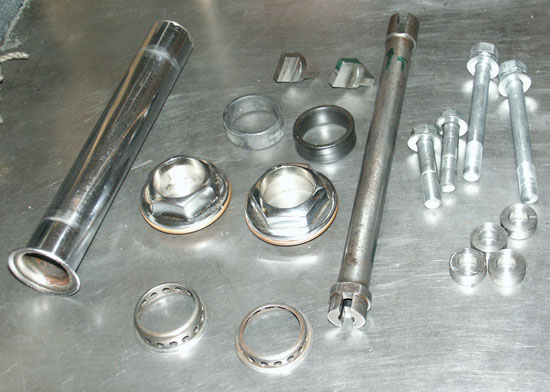
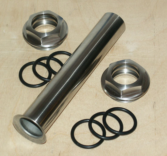
The complete vertical drive assembly, as well
as the vertical tube and gland nuts. Since the original build in 2005
I have replaced the nuts/tube shown here with my own items in Stainless
steel
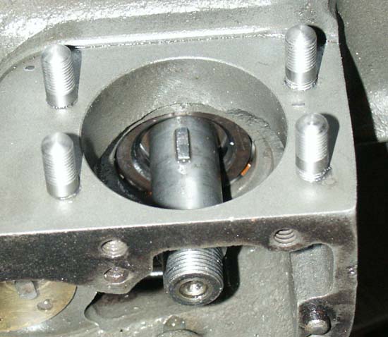
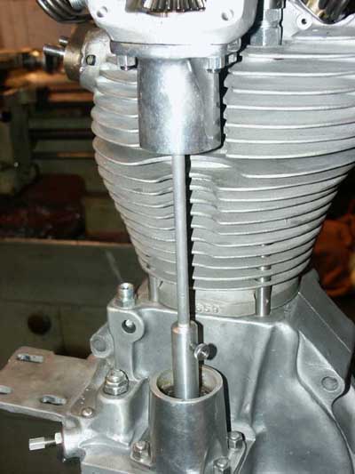
You can clearly see here the large diameter
hole in the crankcase that accepts and locates the lower bevel casting
(in this case an oversize SOHC Manx crankcase)
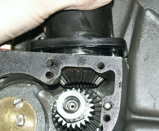
And now fitting the bevel casting and vertical
bevel into that hole. If you look closely you can just see the shim
between them (again, this is actually a SOHC Manx crankcase)
As you can see from the summary above, setting of the correct backlash for each set of bevel gears is covered in other articles, so I will not bother going over that ground again.
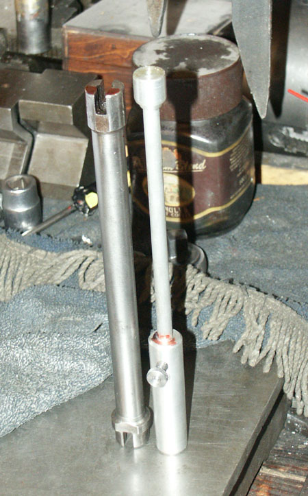
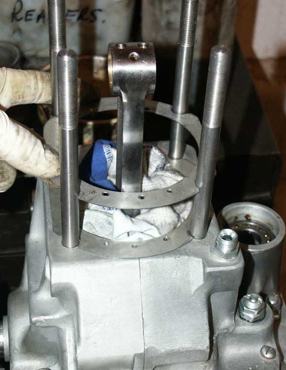
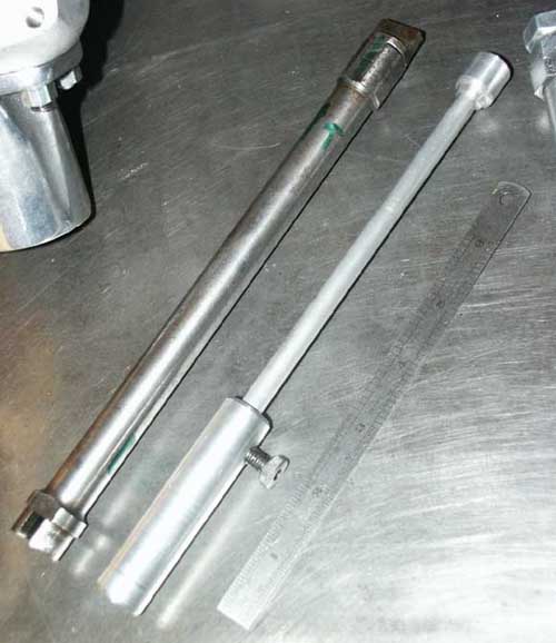
This is the simple telescopic tool I describe in the text that can be used to measure the distance between bevel gears, and from that calculate required Oldham Coupling width
If we pick up from Step 5,
this stage is intended to measure the correct gap between the two vertical
gears, so we can calculate the correct width top Oldham Coupling. I
am sure you will have noticed if you have tried this, that once the
engine is assembled, it is actually very difficult to get a ruler between
the two bevel castings without fouling on the castings themselves. I
suppose if you have gauge blocks or a similar set of engineering measuring
components that could be used to stack between the gap, then it would
be possible to quite accurately measure the gap.
However, I think a far more elegant method is to make up a tool similar
to the one shown in the accompanying photographs, which is as very simple
telescopic ruler, which makes the job of measuring the gap a complete
pleasure!
I cannot take credit for thinking up this device, one very similar was
originally shown to me by old man Judd (of Brabham engine fame, although
he also owned Inters and Manx’s), and is very simple yet very
effective. It consists a piece of aluminium bar approx .5” diameter
and 4” long, bored to take a slimmer piece of aluminium bar approx
.250” diameter. The outer bar has a knurled lock nut threaded
into it, which allows the inner bar to be adjusted telescopically then
locked in place.
All I have to do is assemble the engine with everything in place, except
Oldham couplings and vertical shaft, close up the telescopic tool until
it fits into place, open it up until it is exactly touching both the
top and bottom bevel face, lock it, then make a scribe on the inner
bar where it is flush with the top of the outer bar. You can then close
the tool up, take it out of the engine, set it at the scribe mark again
and measure the length exactly using a vernier gauge or something similar.
If you subtract the length of the vertical shaft + 3/16” for the
bottom bevel, you will be left with the required width of the top bevel
– simple!
Hopefully, you will find like me that the effort required to make the
tool will be far outweighed by the pleasure you get using it, and it
means that you then have it for any future changes of compression ratio.
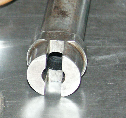
And here is the tool in use
Having gone through all the grief and pain of making sure that you have got this most critical part of assembly correct, everything from this point onwards is pretty straight forward, and more about final assembly than tolerances etc.
First of all, if like me you have done this operation with the engine out of the frame, the next step is to strip the cambox and head off again and do all the other smaller jobs associated with final assembly.
Once you are ready for that final assembly, and you have the head and barrel locked down for the final time, you should be ready to do the final assembly of the vertical shaft, and fitting of the cambox.
These are the slightly modified gland nuts I now supply. As well as being stainless steel they have two internal groovelands to accept modern 'O' Rings, greatly improving their oil retaining properties
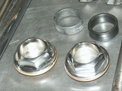
These are the original type gland nuts first fitted, which clearly shows the old type larger rubber seal, which I found were difficult to stop from weeiping oil
Anyway, assuming you are still using the old original type (. . . and my blatent advert above has not convinced you otherwise!), the top one now need to be used to locate the vertical tube. I found before fitting, it is a good idea to smear the seal with a high melting point grease, to help assembly, then you need to slide it over the open end of the vertical tube and slowly move it up the tube until it comes against the beveled shoulder on the far end. Be very careful at this stage to ensure you have no sharp edges or nicks on the gland nut, or have picked up any grit on the rubber seal, as these will very easily find their way onto the vertical tube and leave you with a very prominent scratch the entire length of the tube – remember this is the central focal point of the entire engine!
The vertical tube on Norton Internationals and their other SOHC derivatives were all of similar manufacture, being a steel tube, chrome plated, with a pressed (or spun – not sure which) bevel at one end). The beveled end fitted to the cambox end, the final length then being determined by the size of the engine. There were commonly two types, 500cc and 350cc, but there were also much smaller quantities of the 596cc sidecar units made, which had a longer tube again.
These tubes look externally the samed as DOHC types, but actually the DOHC type fitted to Featherbed engines was wider and not interchangeable.
When first assembling the engine I found it very difficult to find one of these tubes that did not have some corrosion or pitting, and even if re-chromed, the re-polishing of them caused the tolerances to be removed even more, meaning they would be more inclined to leak oil. To jump ahead slightly, having originally assembled the engine using the original type single rubber seals, and a re-chromed tube, I found that the engine regularly leaked a small amount of oil from this tube/gland nut seal, so as well as manufacturing my own nuts, I also looked at having a batch of tubes manufactured from stainless steel.
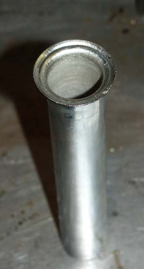
This close up of an original vertical tube shows the distinctive lip on its uppermost end
This shows the stainless steel vertical tubes I am now able to supply in 350cc and 500cc, along with the stainless gland nuts and modern 'O' Rings
Going back once again to the original build, using the original type gland nuts and large rubber seals, the other two items that will require fitting before screwing the gland nut into the cambox bevel casting, is the copper/asbestos ring that fits over the gland nut and the drilled spacer ring. The copper/asbestos ring, part number A11/762, should be replaced every time the nuts are un-tightened, as they crush down and therefore can only be used once. This was another of those items that you could never find one in good condition, and are of a special size, so again, I am able to supply these exactly as per the originals.
The final part that needs fitting before screwing up the nut is the pressed spacer ring – A11/757 and A11/759. I think these serve a couple purposes. First, as you screw down the gland nut against them, one side presses up against the outer race of the ball bearing on the opposite side of the spacer. I found when I was making the castings that these bearings are not really supposed to have more than 0.0005” - 0.001” (between one half and one thou!) interference at most, which is very little. I would therefore conclude that it is probably this spacer acting against the bearing that stops it from spinning in the housing.
Second purpose of the spacer, on the gland nut side, is that it acts as a stop for the vertical tube (top casting) or locator for the tube and stop for the nut (bottom casting). It should be noted that there are at least two sizes for these spacers, the smaller one being fitted on the top casting. However, I have seen various sizes of the larger one. Not sure why this is, but unless you know your spacer came out of the engine you have built, it is worth doing a trial assembly first, to ensure the gland nut does not lock against the spacer ring, before the copper/asbestos ring starts to crush – indicating it is too tall.
Just before I move away from this early DOHC cambox (not my specialist subject!), these early cambox engines are very rare now, as they are the favourite engine of the Cooper car boys. I have been asked if my bevel castings will fit these early cambox’s? Well yes they will, but I gather the original ones were slightly thicker, so the Oldham coupling may need to be a bit longer. If I ever have another batch of top castings made, I may see if the un-machined castings have enough extra metal to allow me to machine one of these later types.
Examples of A11/757 and A11/759 Spacer Rings. I think the larger one is actually as slightly taller version than normal - see text
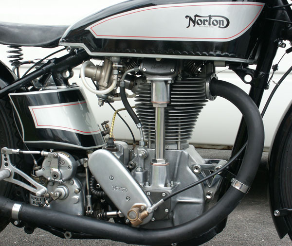
Jumping ahead a bit - here is the the finished engine in the bike which clearly shows off the classic lines of the completed vertical bevel assembly
Final Assembly
So, having fitted the correct spacer and asbestos ring, the gland nut
for the top casting can be wound up finger tight. It is a good idea
not to tighten it up fully until the bottom nut is in. This bottom nut
and asbestos ring should be fed up the tube so it does not get in the
way, when fitting the coupling tube into the bottom casting.
The vertical shaft can now be fitted into the top copling, and held
in place by hand. The entire cambox can then be turned the right way
up and carefully lowered into position on the head (ensuring correct
head bolt spacers are fitted etc). It is then a case of careful ‘fiddling’
of the lower end of the vertical shaft into the bottom Oldham Coupling.
You will probably find this very difficult to locate and it might be
that everything locks up solid before you have the cambox fully tightened
down. This is particularly true if the tolerances are tight on the slots
for the Oldham Couplings into the vertical shaft (which of course they
should be!).
To avoid damaging the bearings, I find
the best approach is to feed the vertical shaft into the bottom coupling
as best as possible, loosely tighten the cambox bolts, then put a spanner
on the camshaft nut (or engine drive nut) and gently rock it ‘to
and fro’, while jiggling the cambox and vertical tube. You should
find that eventually this results in the vertical tube sliding down
the lower coupling slot of its own accord, so it does not lock up and
cause any unnecessary stress – much more satisfactory.
Once you are comfortable the shaft has located properly, but before
the final tightening of the cambox bolts, you should start the lower
thread of the gland nut into the bevel casting, and also finish tightening
the top gland nut. Once this has been done successfully, you can give
the cambox bolts a final tighten and give everything else a final tweak.
Last thing to to do is spin the engine over by hand and ensure it is
not locking up anywhere. You may well find that the top vertical bevel
gear seems to have lost its tolerance and is now tight. This often because
the vertical tube has pushed it up. To overcome this, take an aluminum
drift of approx ¾” diameter and give the top of the bevel
gear a sharp tap with a mallet. This should push the bevel gear down.
A similar operation can be performed on the lower vertical bevel gear
as well, but this requires a lot more care, as there is far less room
with the crankshaft in the way.
Well I think that about wraps it up for the vertical assembly, and depending
the order you assemble the engine, this could possibly be one of the
last jobs that need doing to complete the build.

Return To Top of Page