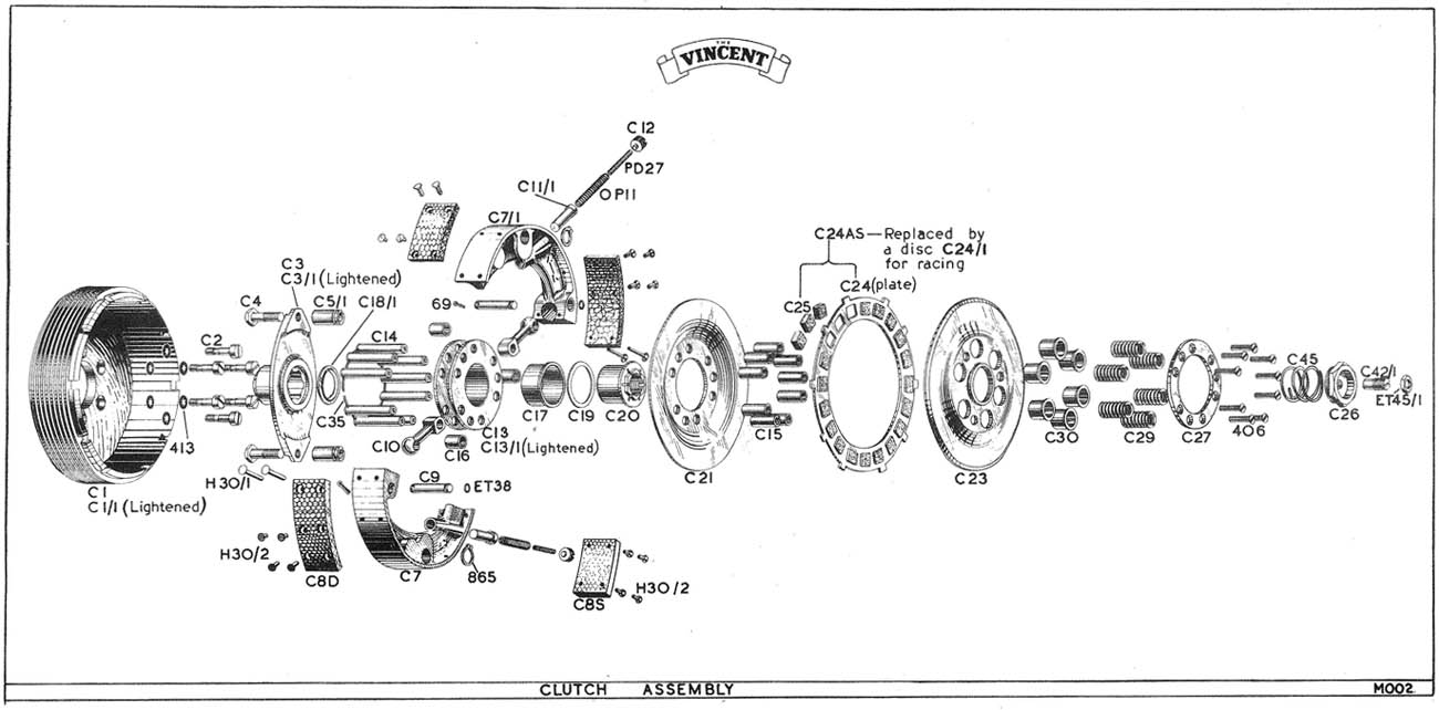
Vincent Catalog - Clutch Assembly Diagram
I quickly realised as I started to write this article that the reader would be lost without this picture to refer to!
Click to see bigger version - then you can refer back to it as you read the article . . . have fun
Article 2 - Vincent Black Lightning Clutch Assembly: September 2012
September 2012 - April 2013: Next Task - Clutch!
It seems like a long time since I gave a proper update on the Vincent lightning build - about 18 months ago actually, so just like buses that come along in pairs, this time I can give an update on two Vincent builds.
Summary of Previous Progress
The last article I did for the long term Lightning build was back in November 2012, where I covered the primary drive assembly. Well a lot of water has gone under the bridge since then and I am pleased to report that other than a few smaller tasks, the build is almost complete, with only the fuel pipes and a few smaller tasks still to do. All through the build I have taken photographs as I have gone along, but with everything else going on, and running the Norton business at the weekends, I have not had time to write articles up or publish any of those photographs. If I get time in the future I will go back and put together more detailed articles of what has gone on between, but as that is looking unlikely for some time, I will use this article to give a summary of progress and publish a cross section of photographs along the way.In the last article I had assembled the primary drive and was just embarking on the clutch. I had already done almost all the mechanical work on the clutch many years ago, including having the main clutch shoes re-lined by Bob Culver and at the same time having the correct spring tensioning of the all-important C11/1 clutch centralising plungers set. Many years ago I was told by Ted Davis that not setting these plungers to the correct tension can be one of the main reasons for the clutch being ‘all or nothing’ and has contributed in some way to the negative reputation this ‘servo’ clutch seems to have gained over the years. If I remember correctly (back in the mists of time – Ted passed away some years ago), Ted recommend going to Bob, as he had the original Vincent jig for setting the tension, but this needed to be set at the same time as fitting new shoes – as one of these shoes then covered the spring tension adjusters. Incidentally, just a few days ago from writing this article (June 2014), I called Bob up to buy some Comet oil pipes and reminded him of this – as well as having fond memories of Ted, he concurred with what Ted had said – that setting these plungers correctly makes all the difference – and yes, he does still have the old factory jigs for doing this.
Clutch Shoe Carrier Pivot Bolt Replacement
First task on the clutch was to replace the Pivot Bolts fitted to the Shoe Carrier. This shoe carrier came with the bike when purchased and was already lightened (see next section). It had pins fitted but these had seen better days. These pins are actually the shafts on which the clutch shoes are mounted so should be in good condition and are easy enough to replace. The original nuts (shafts) are screwed onto a bolt by means of a slot in the top of them. It is then normal to centre punch the inner nuts into the slots, so they cannot loosen in use. As both nuts and shafts were being replaced with new items (from Maughan’s of course, purchased with the rest of the new clutch parts about 15 years ago), there was no need to try and remove them carefully – the easiest method was just to go through the shafts and bolts with a slitting disc in my angle grinder . . . two minutes and job done!Fitting the new ones was also relatively easy, but I wanted a bit of insurance, so used threadlock on assembly when tightening them, and then once I had them as tight as I could get them, I then centre punched the inner bolts at their ends to fill the shaft slot and really ensure they could not unscrew in use. That was the first job done.
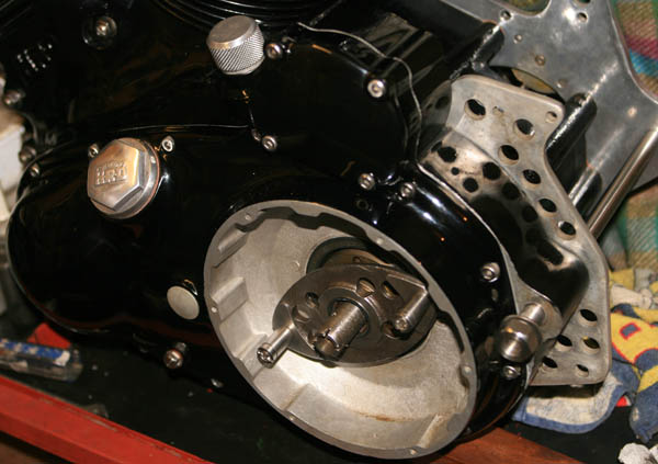
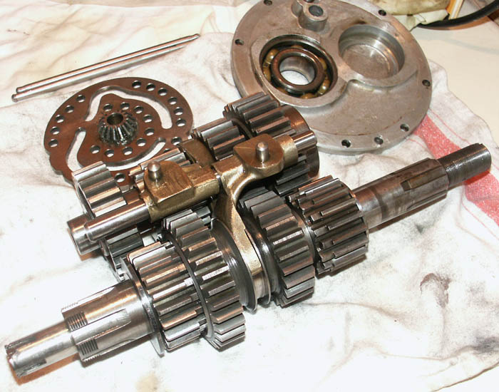
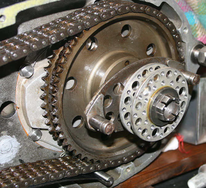
This is where I got to in the last article - primary drive assembled, and Lightning C3/1 Clutch Shoe Carrier trial fitted
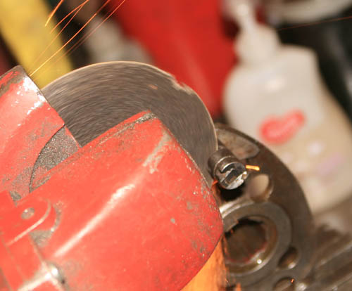
First job was to remove old C4+C5 pins so they can be replaced. No point trying to unscrew as they are punch locked - so just angle grind ends off then they will unscrew easily (note chunk missing in slitting disk!)
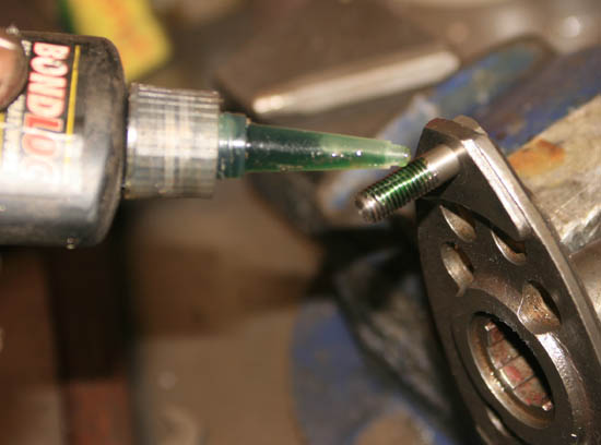
New C4 Pivot Bolts fitted and then ScrewLock applied to threads
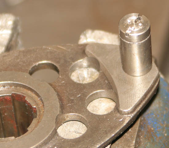
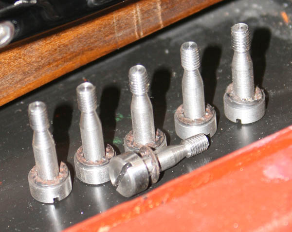
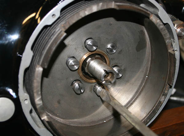
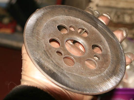
C5/1 Pivot Bolts then fitted (they are called bolts, but proivde a shaft for the clutch shoes), tightened using slot at top, then finally they are centre punched at the top to ensure they cannot loosen in use. This photo also gives a good view of the lightening holes that differentiated a Lightning version from a standard version. Notice spline recess is empty here
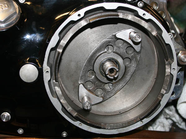
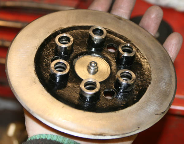
Finished job - Clutch Shoe Carrier refitted with new pins. Note also in this photo the centre recess of the carrier has now had new a C18/1 Oil Seal fitted, which helps stop any oil from the gearbox/primary chain bath getting on to the clutch
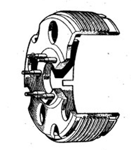
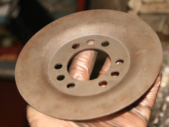
One of the few period line drawings of an early (lightened) clutch drum, as fitted to the first Black Lightnings. You can clearly see the large circular holes and half holes around the circumference. My bike as purchased came with one of these, but I replaced it with a stronger solid one - As Vincent's themselves very quickly did
What makes a Lightning Clutch?
The first difference between a racing clutch and a standard twin clutch is that the single (slow speed) C24AS multi-insert steel clutch plate is replaced with a solid Ferodo racing material clutch plate. To achieve this though, the C1 Clutch Drum has to have its clutch plate slots machined wider to accept the bigger tangs that the solid Ferodo plate has.
Incidentally, the clutch drum I am fitting is a very good used standard item, which looks almost new and came from friend and excellent Vincent engineer – Don Alexander about 20 years ago. I purchased this to replace the more ‘correct’ Lightning specification lightened C1/1 clutch drum that came with the bike when I purchased it. This ‘lightened’ item had large holes approximately 1” in diameter machined in the back of the drum, and ‘half-moon’ segments removed at the point where the back face met the clutch drum. According to literature, this early type lightened drum was standard fitment on the early Lightning’s, but there were soon occurrences of them exploding (probably exasperated by the additional power of the Lightning) and these were soon replaced by the standard ‘none lightened’ variety.
Much as I have always liked the exotic and rare, I did not like the idea of such a critical component going bang, so I decided to replace, unfortunately this was many years ago and the drum has now gone, so I do not have a photo sto show you what they looked like.
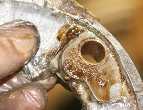
Going back to the standard clutch drum and the solid Ferodo racing plate – to make one fit the other required the slots of the drum being widened and as part of buying the drum off Don, he offered to carry out this task for me (this was about 20 years ago and I had no access to a milling machine in those days). As you can see in the photograph the result is the wider slots and machined finish allowing the fibre plate to just drop in.
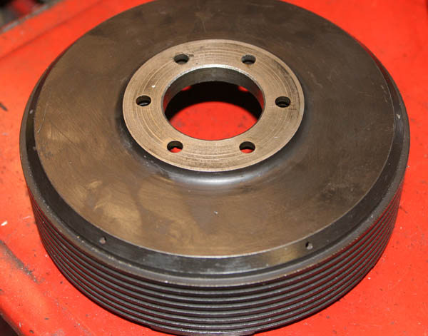
And here is the standard type Vincent drum which I am fitting - nice lightly used condition
C2 screws are beautifully made . . . like so many Vincent parts - these new ones supplied by Maughan's. Very early original scews were individually stamped 'C2'. Lockwashers also fitted here
. . And here fitting the drum. Again, threadlocks was used on the C2's.
In this photo you can clearly see the machining of the primary clutch plate slots to take the solid Ferodo racing friction plate
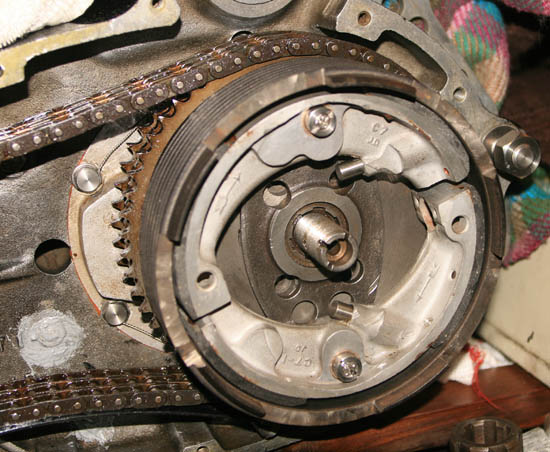
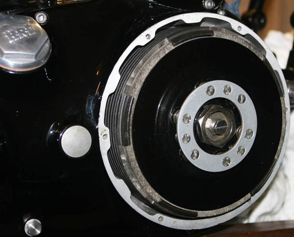
Drum fitted and C3/1 Clutch Shoe Carrier re-fitted
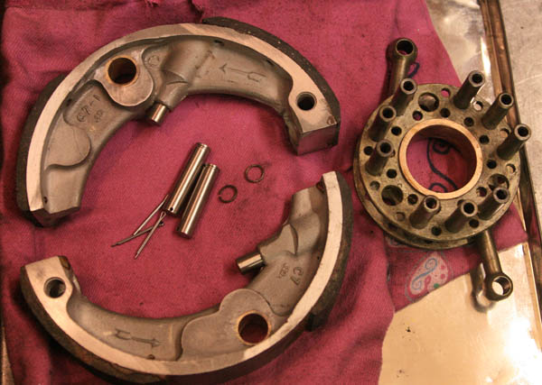
Clutch Shoes
The shoes themselves (C7 and C7/1 – they are ‘sided’ and therefore have different reference numbers) are standard items, as fitted to all twins. As I previously mentioned, many years ago I had new plungers and springs fitted by Bob Culver on his original Vincent spring setting jig, and at the same time he also fitted new bonded linings. When I came to fit them, I found the holes were a sloppy fit on the new spindle bearings, therefore I fitted new phosphor bronze bearings. Originally the shoes were not fitted with bearings, but talking to Maughan’s I gather it is not unusual for them to get a bit sloppy and when this happens they can be bored to take phosphor bearings which they supply (I think they are actually ET64 cam bearings). I was able to do this job myself although not particularly enjoyable as I was worried about getting cutting fluid on the shoes and therefore had to carefully wrap them in clingfilm first.I pondered on if for this job I should mill the holes out, but decided that as I had the correct size reamer it might be easier to clamp the shoes down on my pillar drill table and bore through with a correct sized reamer. This all went relatively smoothly, although I could not avoid just the smallest amount of cutting fluid seeping onto one of the shoes, although I hope this will quickly burn off in use.
Once the shoes were bored it was an easy job to press in new bearings on my bench press and then a final ream of the phosphor bronze bearings resulted in a satisfyingly smooth and wobble free finish of the shoes. I would imagine that once these shoes develop wear in this hole in use, they would cause the clutch to become quite vicious and maybe result in it more prone to snatching - maybe that has helped add to the dubioius reputation and misconceptions the original Vincent clutch has had associated with it for so many years?.
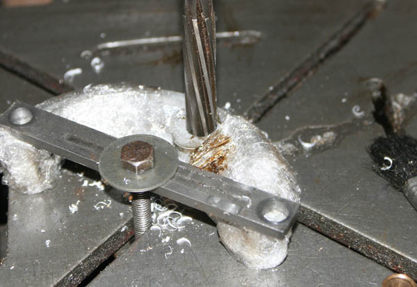
Wrapped in clingfilm, here is one of the clutch shoes being reamered to take phosphor bronze bearings, and pressing in bearing
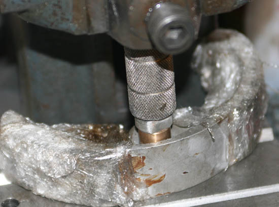
Finished clutch shoe with bronze bearing fitted and reamered
Clutch Plate Carrier and all the small bits!
The C13 Clutch Plate Carrier on a Vincent Clutch is a steel central ‘drum’ with two lips, used primarily to hold the arms (actually called C10 Link Pins) that act as fulcrum points to the clutch shoes – strange then that it is called a Clutch plate carrier, and not a clutch shoe carrier?. Well yes, but actually this central carrier also has holes which locate 9 steel pins (C14’s) which protrude outwards and from which the primary inner and outer plate locate – and it is these that initially engage with the Ferodo friction plate, located to the main clutch drum, which takes up drive and then by so doing eventually transfer that drive to the main clutch shoes (C7)’s as the C10 Link Pins push the shoes out to engage with the C1 Clutch drum. I still have to be looking at the exploded Vincent catalog picture of the clutch as I describe this – it always seems to need some head scratching to understand! Anyway, from walking through this description of the role that the C13 Clutch Plate Carrier performs, you can understand that it plays an important role and a significant load passes through it. With this in mind, a large diameter phosphor bronze bearing (C17) is pressed into the centre of the carrier, which the Clutch Retaining Nut (C20) fits through. As well as ensuring this holds the C13 central under load, the bearing face allows the C13 to turn radially in relation to the other moving parts, as the primary plate drive is taken up.
Converting C13 to C13/1
So having explained the construction and theory of this part of the clutch design, back to my own clutch build. As purchased, my Vincent came with a standard C13 (i.e. undrilled), but somewhere along the way (I vaguely remember it was from the late Val Blower in Hinckley from whom I bought a number of Shadow parts), I also acquired a second C13 . . . probably because I knew that in having to convert a standard C13 into the drilled/lightened C13/1 used on a Black Lightning, in doing so I might make a mess of one of them!
Eddie Stevens in his excellent book ‘Know Thy Beast’ gives the correct drill size and hole pattern for converting the standard C13 into the lightened C13/1 version fitted to a Black Lightning. I am not sure how much difference this hole drilling process achieves – other than making the finished article look very pretty, but I suppose again it was an attempt to reduce reciprocating weight and help aid in smoother/faster gear-change’s. Well as this is one of the feature’s that differentiates the Lightning clutch specification from both Rapide and Black Shadow, I wanted to replicate it – so first of all careful marking out with scriber and ruler was called for, followed by centre punching. It was then just a case of very carefully and laboriously drilling out the hole pattern, first of all with a small pilot drill, and then the correct final hole sizes. I was pleased to find that, although not soft, the C13 base metal was not hardened as I suspected it might be. I think the whole process took a couple of hours and once done I gave it a quick coat of protective etching paint to stop the worst of the corrosion – particularly as the Black Lightning clutch cover will have vents in it to keep the clutch cool – but be more prone to letting in the elements.
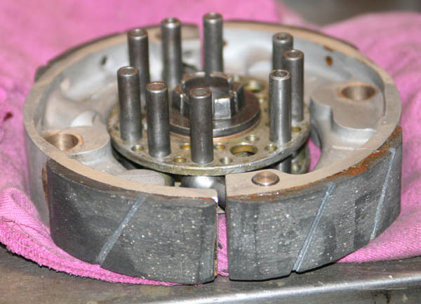
And now trial fitting of shoes on shoe carrier before attaching the shoes to all the other gubbins. Notice that both shoe plungers are on the same side (i.e. the shoes are 'sided'). That had me confused for a while as well.
Next step was to assemble shoes over the C13/1 Clutch Plate Carrier (the drilled bit in the middle in this photo!). This photograph was actually taken at an earler stage of the build, but shows the C13/1 carrier off well
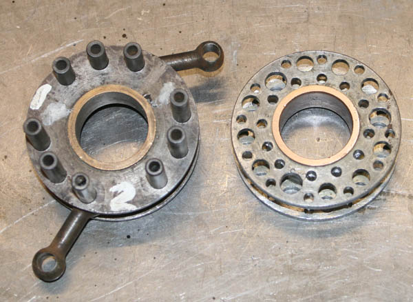
Comparison of standard C13 (with link pins and C14 pins fitted) with lightened C13/1 next to it
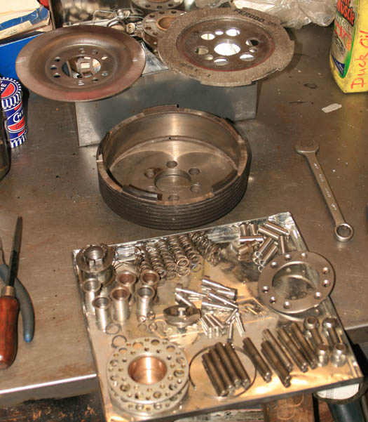
This photo shows just how many parts there are in a Vincent twin clutch - including a whole host of smaller parts
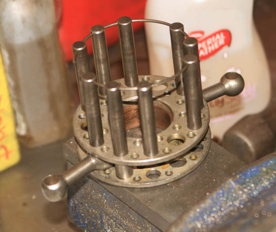
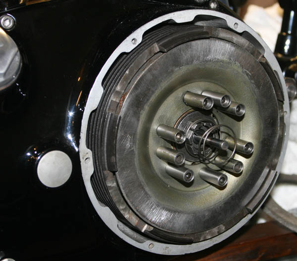
Assembling the 9 C14 steel pins and 2 C10 Link pins around the C13/1. They are held in place by a spring wire (C35)
Shoes about to be fitted to C13/1, showing new stainless C9 Clutch Link Pins, with the tiny circlips and split pins that are used to attach the end of the shoes to the C10 Link pins (i.e. the arms fitted to the C13/1)
Assembling Shoes on Carrier and The Other Gubbins
Having finally completed the preparation of all the myriad of parts that go to make up this ‘servo’part of the clutch, at long last I could commence assembly. I would like to tell you it was all simple and straightforward, but that did not turn out to be the case! Frankly, as I write this article a year or so after actually doing the assembly . . . I can only remember the annoyance of having to repeatedly assemble and dissemble all the little parts and spacers around the C13/1 until eventually I found a combination that looked about right – then pushed all the C14 pins fully through the C13/1 (remembering they are all held roughly in line with the C35 circular spring wire), getting angry because they would not go through easily with the light anti-rust paint I had mistakenly daubed on them before assembly, then realising that particular combination did not look right and having to start all over again. After many fruitless attempts, scrapings of etch paint all over the workbench, and broken finger nails - I reverted back to the Norman family tradition of F**ing and Blinding at the bloody thing, hoping that would somehow help all the parts magically assemble in the right order!
I am sure there are more experienced Vincent people than myself reading this and thinking - ‘what were you farting about at?!’ but I have to say – ignorance is not always bliss and in my case early attempts were about as successful as the last time I picked up a Rubix Cube!
Eventually, having exhausted every possible other combination, I finally got the C13/1, Shoe Carrier and clutch shoe combination all together in one wobbling mass looking vaguely correct, and was able to transfer it to the clutch housing itself where I could mount the Shoe Carrier on it’s spline and fit the C13/1 central, so the large shouldered C20 nut (not forgetting the C19 thrust washer that fits behind it) could be fed through it, and then tightened – which it does by abutting a shoulder on the gearbox mainshaft, the end result being that the C13/1 was left nicely ‘floating’ and able to turn independently of the gearbox mainshaft – allowing shoes to move outwards as speed increases. As shown in the photographs, once shoes and carriers were all in place, last task was to ensure the two clutch shoe retaining circlips (865’s) were fully in their grooves and check they did not in any way impede the free movement of the shoes.
The diagonal grooves in the clutch shoes were added to aid removal of dust (advised in Eddy Stevens book 'Know Thy Beast') - careful use of a hacksaw easily achieved this
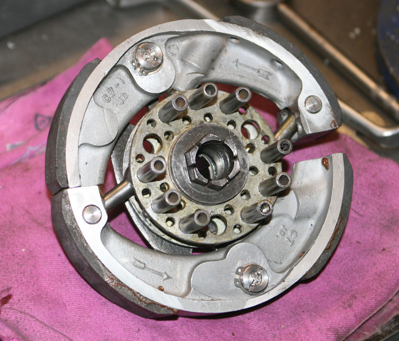
Getting everything assembled to this stage was a fiddly and time consuming process - but now ready for the whole assembly to be fitted to the clutch itself
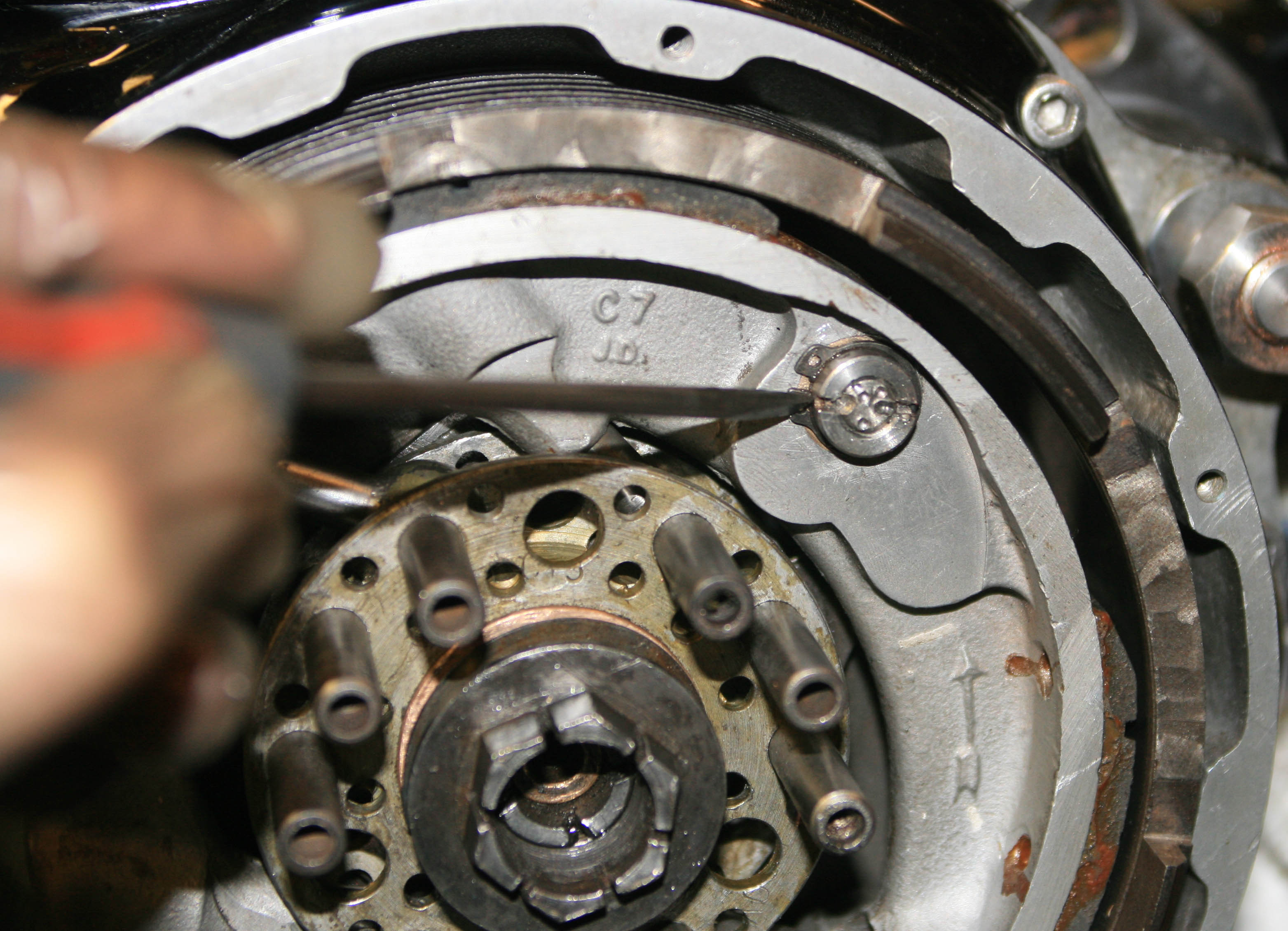
Last task after fitting the assembly to the clutch is to ensure the clutch shoe retaining circlips can rotate, indicating they are seated properly and not fouling the clutch shoes
Primary Clutch Plate Assembly
C21 Inner Clutch Plate, with light surface rust, looking just as it did when I first purchased the bike 25 years ago
Now We Start Work on the 'Pimary' Clutch Components
What is unusual about the Vincent clutch is that it is effectively two clutch mechanism’s in one – a simple single friction plate ‘primary’ clutch, which engages for moving away and slow speed, and then full load where the servo type clutch comes into play.
Having assembled the more complex servo clutch (I am sure my referring to it as a ‘servo’ clutch is offending numerous more knowledgeable Vincent owners) the simpler and more normal multi-plate clutch felt like coasting downhill! As covered much earlier in the article, the most difficult job associated with this was machining the drum to take the solid Ferodo plate, which was done many years previous. Also done at the same time was actually purchasing the solid Ferodo friction plate, which came with Maughan’s, like so many of the other new smaller clutch parts. I am quite pleased I bought the plate so many years ago, as I have an idea that Ferodo racing compound clutch plate compound is no longer available – asbestos content no longer within Health and Safety rules me-thinks.
When I first bought the bike, amongst the clutch items were good solid rear clutch plate (C21) and outer plate (C23) in similar condition. Both had some cosmetic corrosion, but nothing serious (after all Vincent transmission parts as a rule look like they are made for tractor’s, so a minor amount of surface rust does not even scratch the surface!). Slightly more serious was that both plates bonding surface looked corroded, scored and uneven – therefore would not give their best in use.
With this in mind, first task was to totally derust both plates – easy-peasy when you have a big 8” rotary wire brush on a pedestal mounted bench grinder.
The bigger job was to clean up and true the plates back up, removing the grooves and uneven surface. However, this job did not concern me that much either – having the benefit of a linishing table in the workshop, which employs a large revolving emery cloth band over a steel table (and since doing this job about 18 months ago, I have subsequently purchased a larger more industrial version of the same – very good at reducing fingernails if not careful!). By placing both clutch plates face down on the linishing tables as the emery band is rotating (wearing gloves), keeping a firm grasp on one end of each plate, which overhangs the linishing table, I was able to then keep revolving the plate, so it was not picking up a gouge or channel in any one point. I cannot advise this as a ‘preferred’ method of carrying out this task – as I am well aware it could be considered a bit dangerous, and not easy to perform, but having had lots of experience with this method myself, I was able over a period of a couple of hours to get very good results – achieving an overall flat surface to both clutch plates and remove all the deep radial grooves. I found the secret to this job was to not rush it, make sure the plates are held absolutely flat to the table (not easy when the linishing belt is trying to throw it out of your hands) and constantly cool the plates down by keeping an ice cream tub of water close by.
The finished result looked much better, as well as giving the plate surface a nice ‘scrubbed’ effect, which gave me some confidence they will be more effective in use than how they were when I started.
And here it is fitted - having been de-rusted, the plate face having been linished and the inner section rust protected. Note pushrod and light spring (C45) are fitted here, as well as new stainless C15 sleeves over the C14 Clutch Plate Pins
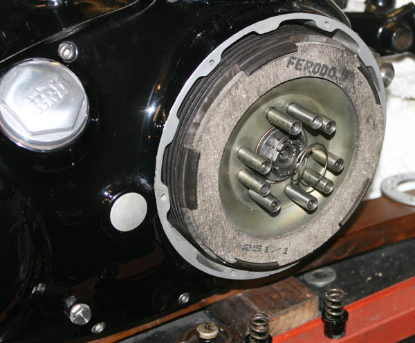
And next - with the racing Ferodo solid friction plate (C24/1) in place. Manx Norton racing clutch plates used to be made in a similar way - I still have a couple of originals
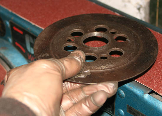
Linishing the Outer Clutch Plate, to restore a flat surface. New belt fitted for the occasion. Although the photo does not do it justice, once the belt is in motion - it has a tendency to turn the clutch plate into a flying saucer. I have since replaced this linisher with a bigger more industrial version
C23 Outer Clutch Plate with linishing in progress. At this stage you can still see corrosion marks midway round the plate, indicating there is still more to come off. Notice the centre plug not fitted yet
Fitting the Primary Clutch Plate Mechanism
This final assembly task was much simpler than the earlier servo mechanism, starting by placing the C21 over the C14 clutch pins, with the dished centre being recessed.
Then fitting the nine stainless steel C15 sleeves over the clutch pins and placing the C24/1 Ferodo racing friction plate in place in the (now much bigger) slots of the clutch drum. I also fitted the C45 spring (although I am not sure I really understand the principle of this spring – it must be there for a purpose, and I assume it is to hold the plates apart when the clutch lever is held in, but would not have thought it is needed?).
With the outer clutch plate, having been linished and its working surface looking much better, I gave it a coat of black paint inside and out, and then fitted the Clutch Thrust Plug (C26), which I had previously had chromed, knowing that on the Lightning it is normal for the clutch cover to have a hole in it to allow access to the clutch rod adjuster, therefore wanted this item to look cosmetically nice.
I had previously bought new clutch springs, clutch spring cups, C27 Clutch Spring Ring and the small countersunk 407 clutch screws from Maughan’s many years ago, so having fitted the spring cups and springs into the outer clutch plate it was a simple and satisfying task to finally put the outer clutch plate in place and then slowly tighten up the nine clutch screws in sequence, so the tension in the springs was taken up evenly all the way round. Final task of the whole assembly was to adjust the central clutch rod adjuster and locknut so that the clutch lever was just taught, and as soon as the lever was pulled in, it lifted the clutch plate.
. . . and the completed job. Consistent linishing all around circumference of plate indicates grooves are gone and it is evenly flat. Notice also spring cups, springs, and centre plug with ball ended adjuster all fitted
The finished job - completed Vincent clutch looking very purposeful. The clutch run's dry (or at least - is intended to!), but still needs a cover to avoid you removing chunks from your left boot
And here is the inside face of the clutch cover. Like many Black Lightning covers, it has holes and segments taken away from it, to allow the airflow in, but if you look at the top of the photograph you will see I have Araldited in aluminium gauze for the two frontal areas , to avoid the worst of road debris
First photo shoot outside with bike on wheels and engine unit complete, shows clutch unit to be unobtrusive. I later painted all the aluminum faces and mesh with black paint, which looked much better
Reflections On The Vincent Clutch
Having spent a considerable amount of time on the assembly of this clutch – it has given a good insight into the mind of the people that had designed the Vincent, people like Phil Irving and Phil Vincent who must have spent considerable time mulling over how they could improve the HRD Series A twin – of which one of its acknowledged weak points was the pre-war multi-plate clutch (which I think was a Burman design).
Again, as with so many features of the Series B/C twin – I cannot help but feel that it was designed primarily by engineers less concerned with practicality or simple maintenance than they were with finding the best theoretical solution. Although I really enjoyed working on it (most of the time) and marvelled at the amount of thought that had gone into the design – I can see why it had a reputation for being difficult in operation and maybe overly complex for its intended application, after all, there have been literally hundreds of far more powerful motorcycle designs since, that have all relied on a simple multi-plate design and have handled the power and torque with little complaint.
I will not know how well the clutch works until I ride the bike in anger, but I was pleasantly surprised to find that, having plugged up the clutch cable and attached the rear chain a few weeks later, pulling in the clutch lever with the bike on its wheels and the bike in gear, resulted in the clutch freeing quite easily – indicating that at least the multi-plate component seems to be doing it job as designed . . . we will see.