Early Douglas Logo - 2 3/4 HP engine being held aloft
Douglas 2 & 3/4 hp Progress - Part 2: November 2018
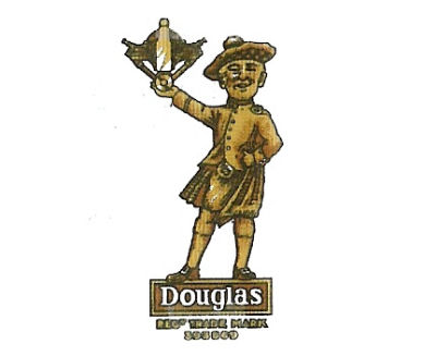
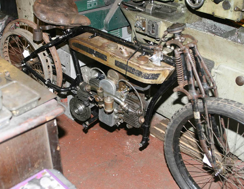
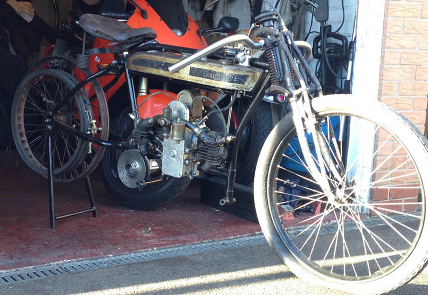
Douglas loosely assembled in workshop in July 2016 - just before fitting handlebars and taking to Brooklands. This workshop was shortly taken over by CNC lathe and both this and the Gardengate Manx kit in the background were evicted to a new area
Douglas engine looks quite complete in this photo but is only loosely put together to give me an idea of what parts are missing and if things generally fit before stripdown
Douglas Build Progress Part 2 - Late 2016 to Nov 2018
First of all - I cannot believe it is 2 years since I wrote the first article on the purchase of my Douglas 2 3/4hp build project from Bonhams April 2016 Stafford auction . . . and given the amount of time passed, you would have thought it would be finished by now - but lets start by saying up front. . . it is'ent!
Instead, the last 18 months has been mostly about running the Norton SOHC parts business - which has been pretty all consuming (alongside my day job), particularly since we now do much of the CNC machining in-house. This has been a very succesful addition to our capability - and allows me to manufacture many more special parts and makes quality control easier, but the downside is that I have found weekends have been wholly taken up by the process of doing drawings (Autodesk Inventor), writing CNC programs and then setting up and running the machine - before I know it, it is Sunday night - and as I finally complete a batch of new parts, I realise I am back in the day job in a few hours time!
So with this backdrop, I decided earlier in 2018, that I ought to try and at least do something on one of my own bikes each week - there does after all seem little point building a business to make parts for classic bikes - which for most people are a hobby, and then never been able to indulge in the hobby yourself!
So this article goes into a bit more detail of the earlier build tasks I did get done in the latter part of 2016 and early 2017, and how the build itself has progressed since I resumed work in early 2018.
It also includes photos of some of the additional parts I have accumulated over that full period of time - as if you have been reading my Blog page you have may have seen that I have caught the 'Douglas' bug, and am already thinking about the next flat tanker project - maybe a replica of the first OHV flat twin, a 350 built for the 1913 Works Douglas team, based on the 2 3/4hp crankcases - of which I have a spare engine.
(as always - click on any photo to see an enlarged version)
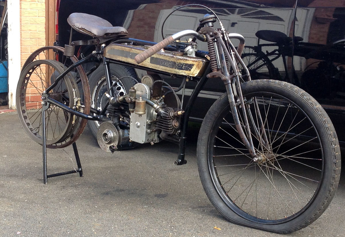
And here is the Douglas with the special 'TT' type handlebars fitted, as it was when I took it to Brooklands in 2016 (see first Douglas article and subesequent Brooklands article - both listed in our Blog section). In the few photographs I can find of the 1912 'Works TT' Douglas bikes, these handlebars were mounted below the top fork links - as shown here, while all production bikes show 'bicycle' style handlebars which had the normal 'T' type mounting with a vertical tubed fitting through the headstock. Although not really correct for a bike of this era - this type of mounting has allowed me to fit an early Andre steering damper I have - which I have been looking for a use for for many years. Although the damper is probably early 1920's era (it has the original mount to go on a flat tank motorcycle), I like it and think it gives the bike more of a competition feel.
As a reminder, the engine and frame date the bike as 1920, but the front forks are actually the earlier pre-1918 type, as fitted to the early Works racing bikes, more about these forks later on - but the previous owner had put a label on them saying there were of 1914 vintage and highly original including fittings
Post Brooklands Strip Down and Build Tasks - And Finding Missing Parts
So going back to the second half of 2016, having worked quite hard to get the overall mock up of the bike loosely assembled in time for the Brooklands Reunion meeting - a definite success and raised many favourable comments, I decided to take the mock up no further - it had served it's main purpose of allowing me to trial fit many of the smaller parts I had worked on or fabricated, and instead I would start the more normal restoration and refurbishment process, that meant stripping the bike down again.
However, the Brooklands meeting had given me a bit of a moral quandry. A number of people at the meeting, including some old friends had said to me it looked great as it was - i.e. very oil rag, and looking like it had just been pulled out of a barn. Yes - it would definitely have appeal if I could just make it roadworthy enough to use it as it was, however, I was well aware that when you got up close - numerous parts of the bike were too rough to use as they were - for example - I knew the fork spindles were locked up solid with rust and would definitely need refurbishment, and other parts were similar. Therefore, after much deliberating, I decided I would strip and refurbish, and see how things progessed from there. I knew I wanted to nickel plate many of the parts as they were either too badly corroded as is, or just not plated at all - but many of the fastenings and cycle parts were missing or too rough to re-use, and I knew I would therefore re-make these from stainless steel, which also resembles nickel plate when polished.
But then in Autumn 2016, before I could really progress further on with this particular build - a major distraction in the form of a very nice second hand Emco 325-II CNC lathe came my way, and with this all efforts moved towards getting this setup and working, and through this necessity my focus needed to change. I have covered the setup of this CNC machine elsewhere, so I wont cover it here - but it meant that rather than starting the Douglas stripdown immediately in Autumn 2016, I decided to leave it as it was - and instead just do smaller build tasks as I got time, and try and accumulate some of the many parts I knew were still missing.
Back to 2016 - First Getting Bike In Workshop and Stripdown Tasks
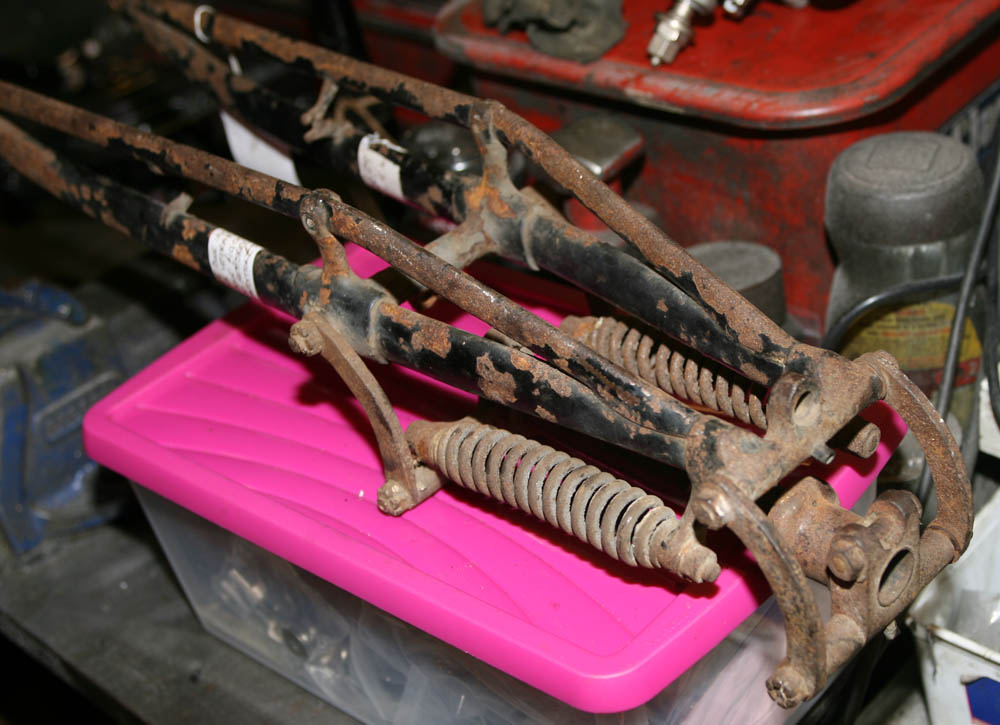
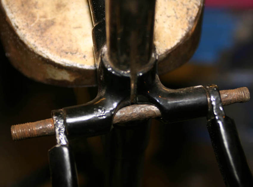
Front forks - wonderfully original and unmolested - and still with what i assume is the original paint on them
Fork yoke has original paint - this would have been hidden in frame head stem. Notice original castellated Douglas nuts on spindles. I did find a disturbing period photo of an early race bike fatality of a Douglas rider on the internet, where it looks like these springs may have snapped - slightly unnerving!
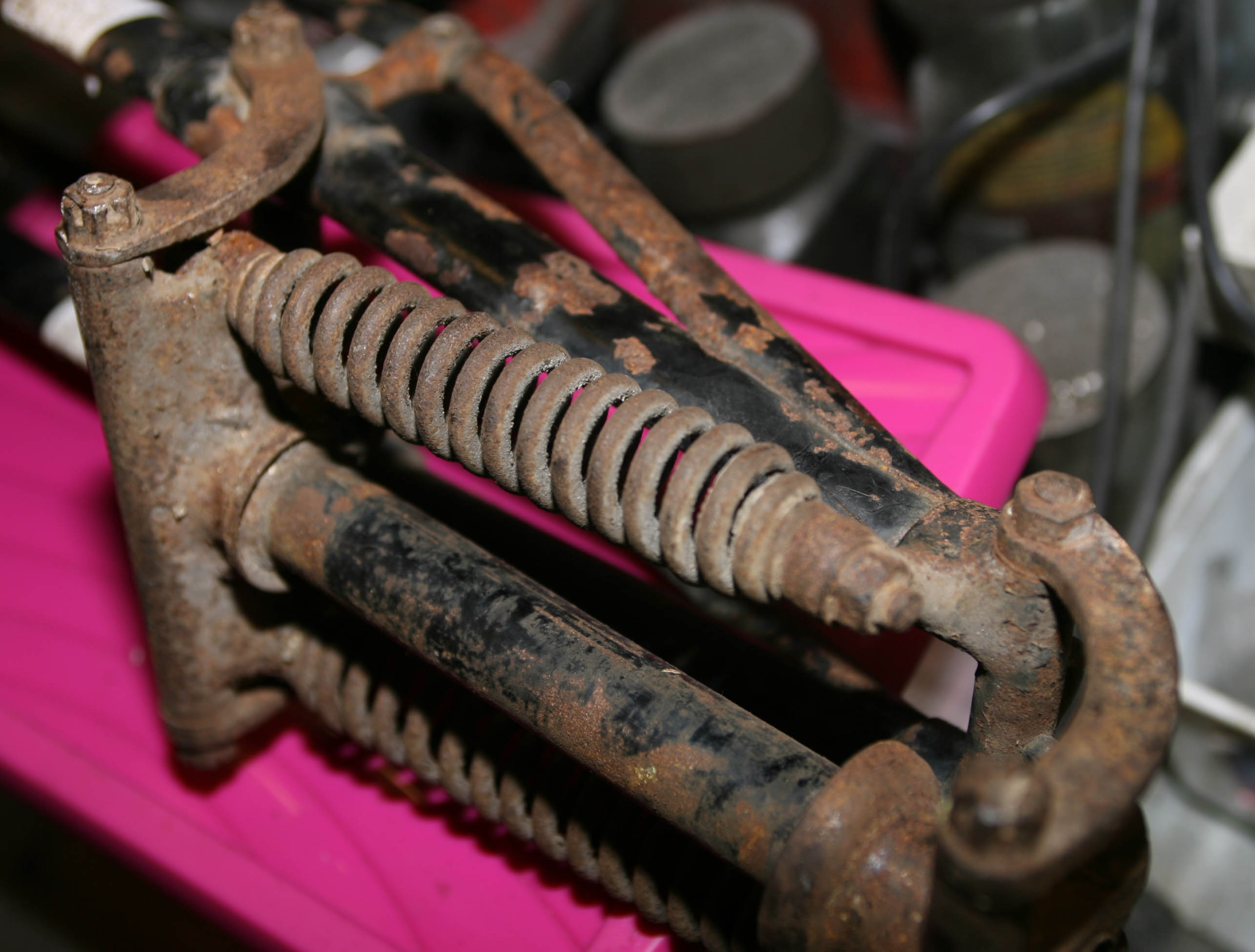
Removing spindles was a bit difficult as they had locked up - but once out it was easy to see why . . . these gave the impression it may have been the first time they had been stripped down in over a 100 years!
Lovely and original, but I think I may have to make new ones - and maybe slightly oversize, as the forks do not look to have enough meat on them to allow bearings to be fitted
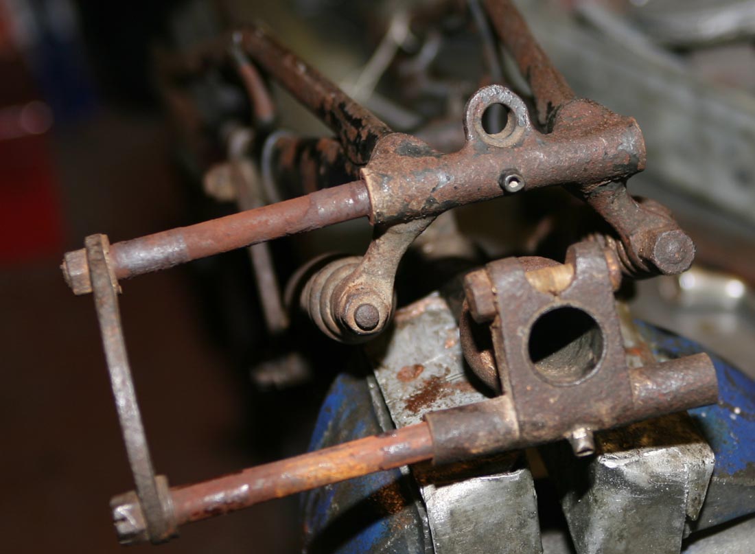
Here I have fork stem held in vice with soft jaws, while I try and remove top fork yoke off stem, again very stiff after many years of languishing
Central lug on the top casting of the fork blades is the mounting point for the front brake cable adjuster - re-threading that did cause me some issues later on, of which more later
Top crown - or as Douglas called it - Head Clip. At this stage it has been cleaned of all the surface rus and like most parts of the fork are in overall good conditions. Wear in spindle holes does not look excessive (more of these in a future article) and although you cannot see it - the ballrace underneath had only marginal wear. Two points of particular interest - first the period brass grease nipple - fortunately in good usable conidtion. And then the lock bolt. Notice it has a rounded head but a cross-drilling to take a small pin. There is then a corresponding cross drilling in the Head clip to ensure the bolt does not slip. I have now had the bolt nickel plated and shall make up a new pin
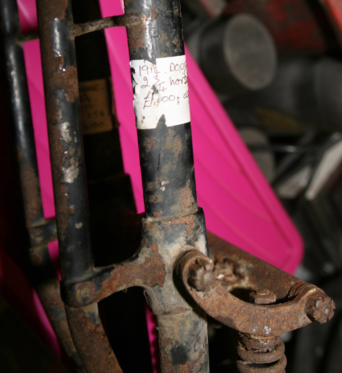
Previous owner looked to have attached a label to the forks at some point in the past (or maybe that was the price tag when he bought them?) that they are early 1914 Douglas forks for a 2 3/4hp, with a value of approx £1000. Hard to say what a set would go for on Ebay - but I know they are extremely rare, particularly in such original and untouched condition. It is now almost 3 years since I first purchased the Douglas and I have been looking for a second set of these early blades for a second bike since, to no avail as yet.
There is some debate of the period these early type forks were fitted. The original parts catalog lists them from 1912-19, but you can see period photos of the later (stronger) forks fitted as early as 1917. I am told they were still using up old stock of the earlier type for some time afterwards.
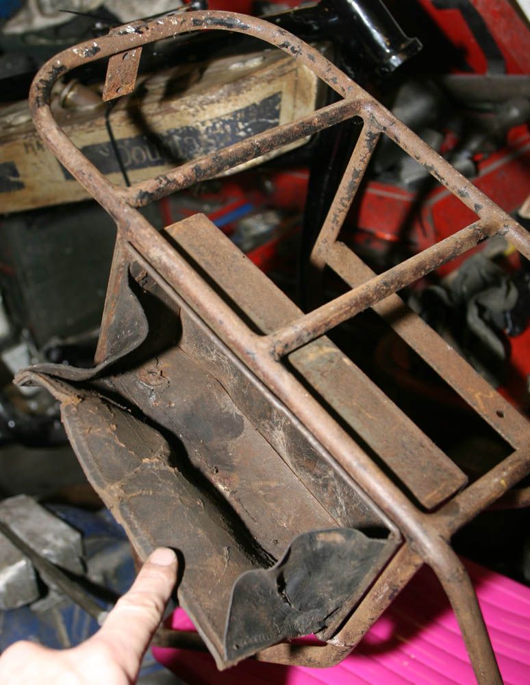
With the parts in the Lot there was also a nice period rear carrier and one toolbox. The carrier has quite a bit of rust on it, but is still very solid, so will clean up well.
Tool box has remains of leatherette frontage and original paint (see below), but unfortunately has tin worm at its base. I will try and put in a new plate over this, as well as a new front cover.
General shape of the carrier can be seen here, including clip at rear for rear number plate. The attachment points at base of carrier do not seem to marry up to rear subframe - but I will figure that out later
Not entirely sure what the clip on the lower left rung is for, it lloks like it may be for a beltguard or similar - but is on the wrong side for a 2 3/4hp?. There were so many similar models made over that period, it could be this particular carrier was origtinally fitted to a different model . . . but I have seen period photos of 2 3/4hp models fitted with carriers of almost identical shape - and I want to use as many original parts on this build as possible - so I will make it fit!
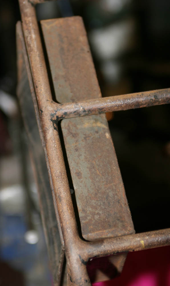
And here is one of the giveaways that this toolbox may have had a poignant history - traces of what look like WWI shade Khaki on it, indicating it was originally fitted to a WD Douglas. I will sympathically rust treat it, but will try and keep a little bit of the original paint as a reminder of its past
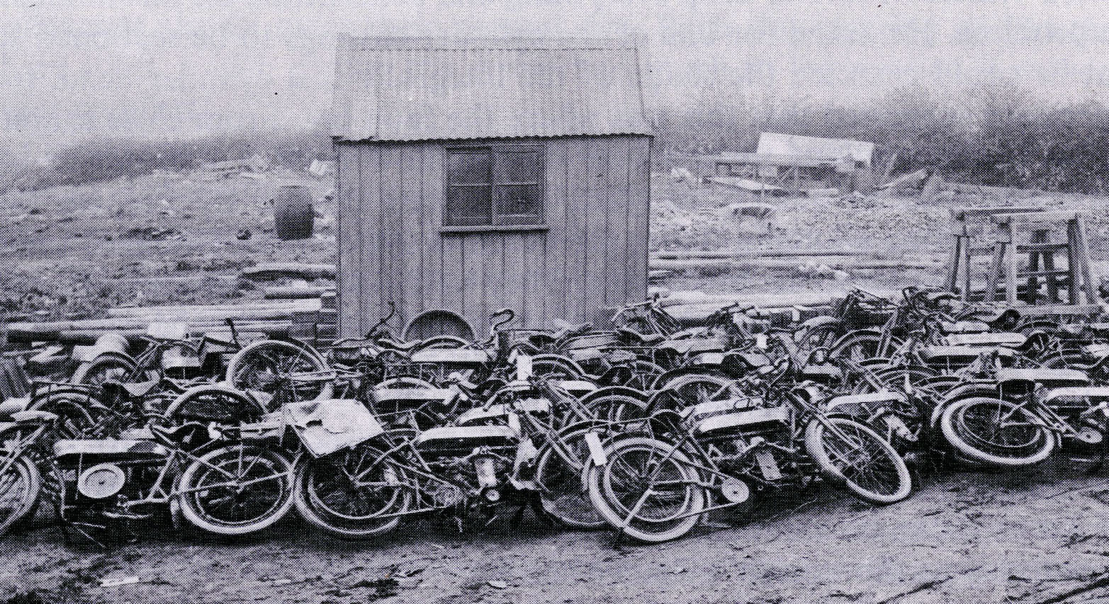
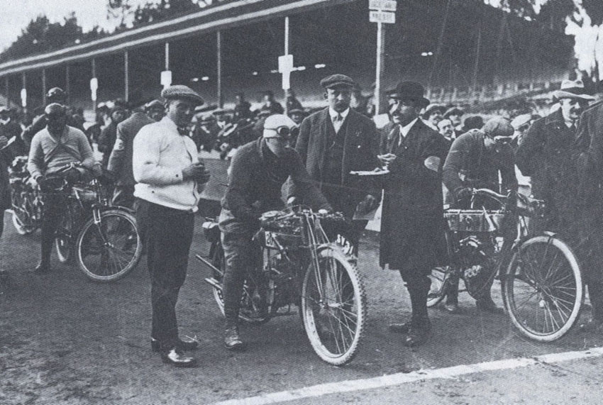
The photo below is a period shot taken I believe in 2018 at the end of WWI hostilies, showing a collection of WD Douglas 2 3/4hp models in France, waiting to be sent back to UK for refurbishment. I have some old copies of the 'Green Un' from the late 'teens, showing these refurbished bkes were still being sold at premium prices - as new bikes after the war were not easy to come by
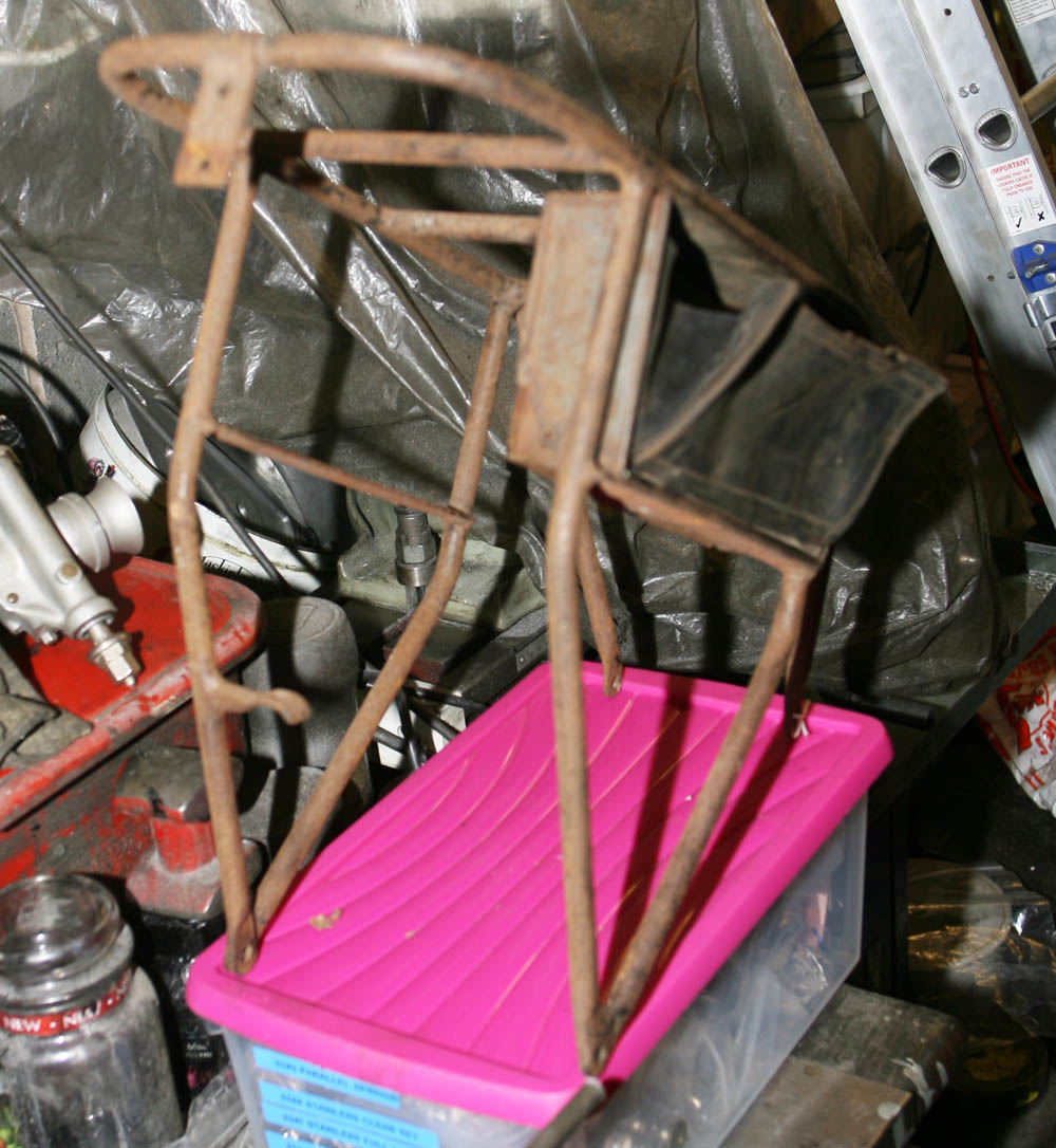
Along with the rear carrier - the project kit also included a rear stand. On initial inspection it looked very rusty and frail, with one leg a bit knocked about. However, it also looked period and correct for a Douglas 2 3/4hp stand - which was the important thing. After cleaning off the worst of the rust - for some reason I decided to give it a coat of paint, knowing I would need to come back to it and do more serious work to restore shape and finish
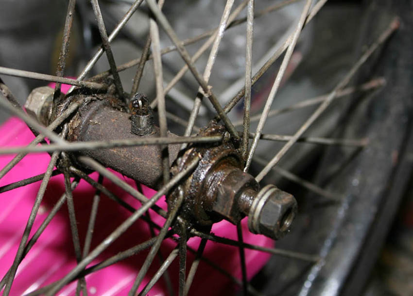
Front wheel that came with the bike was in better condition than the rear, but although the hub is nice and period, I do not think it was originally a Douglas 'own brand' , more likely a proprietary hub. No matter - it is of correct period and spoke pattern and looks right. It subsequently cleaned up well. Again, note lovely period grease nipple
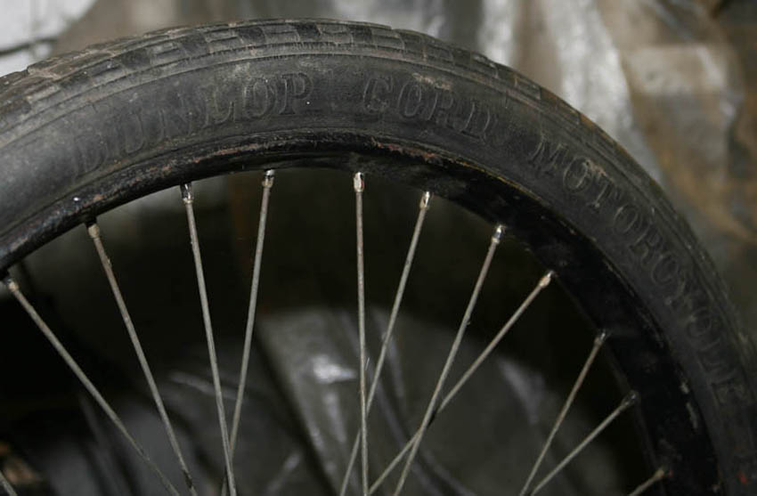
Front wheel again - still fitted with period early 1920's Dunlop Cord beaded edge tyre. Nice to put up on a wall as a momento - but definitely not usable!
Having inspected both I noticed that the front wheel rim was actually wider than the rear rim - the Dunlop tyre size stating 26" x 2 1/2". This was a common size fitted to Douglas 2 3/4hp models from 1920 onwards. However, as I subsequently realised - because I have the earlier (and slimmer)
front forks - which I want to use, I would need to rebuild the wheel with the pre-1920 type 26" x 2" beaded rim size. On close inspection, neither wheel rim looked safely reusable - so this was not an issue - other than finding replacements!
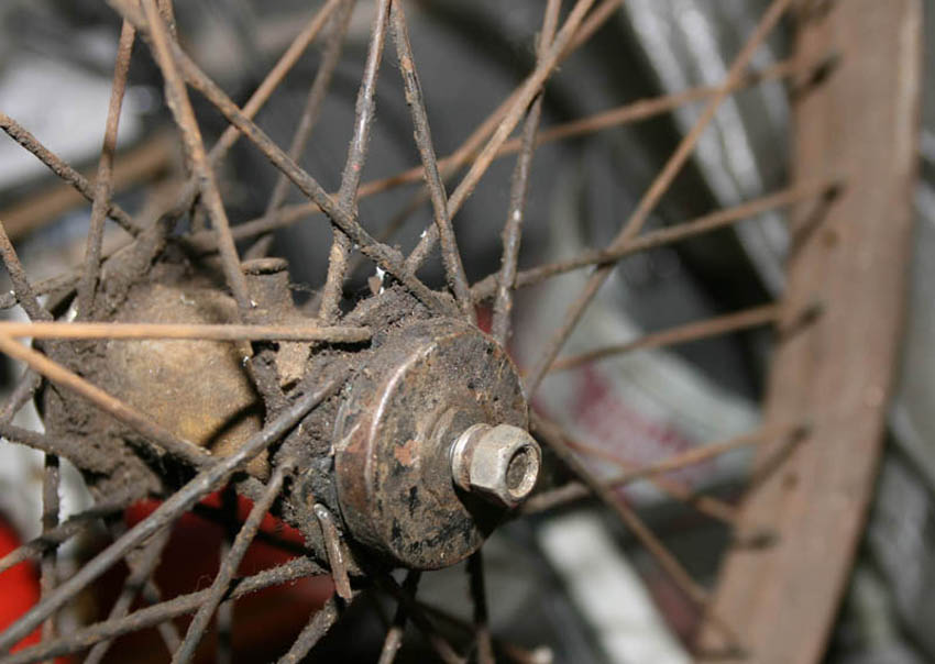
Rear wheel was a very early and genuine Douglas 2 3/4hp version of the type and size fitted from 1912-19 - as the rim was an early 26" x 2" type.
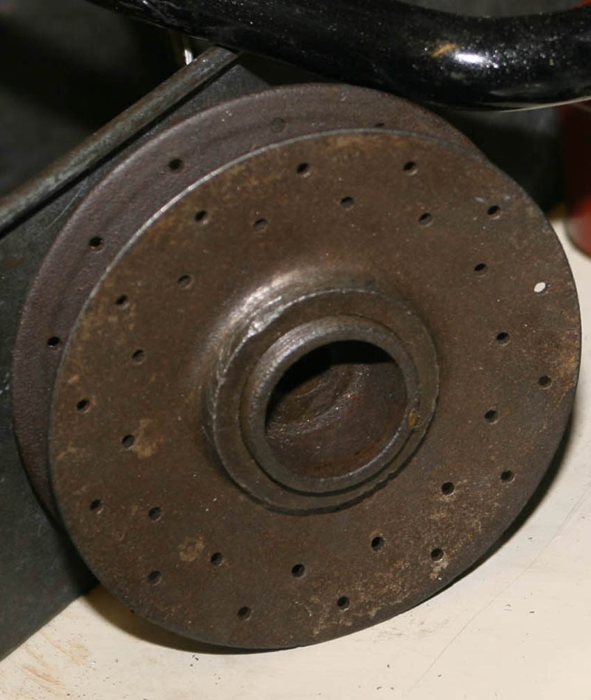
Although the rim was badly corroded - and ultimately not reusable, it was a fantastic time warp item. Look at the little diamond plates under each spoke head - of which I was able to salvage a few for possible future patterns. The hub itself although looking rough in this photo, was caked in 100 year old road filth and oil that had turned to a tar like surface - which had actually protected the original Douglas hub very well. More of this hub in a future restoration article
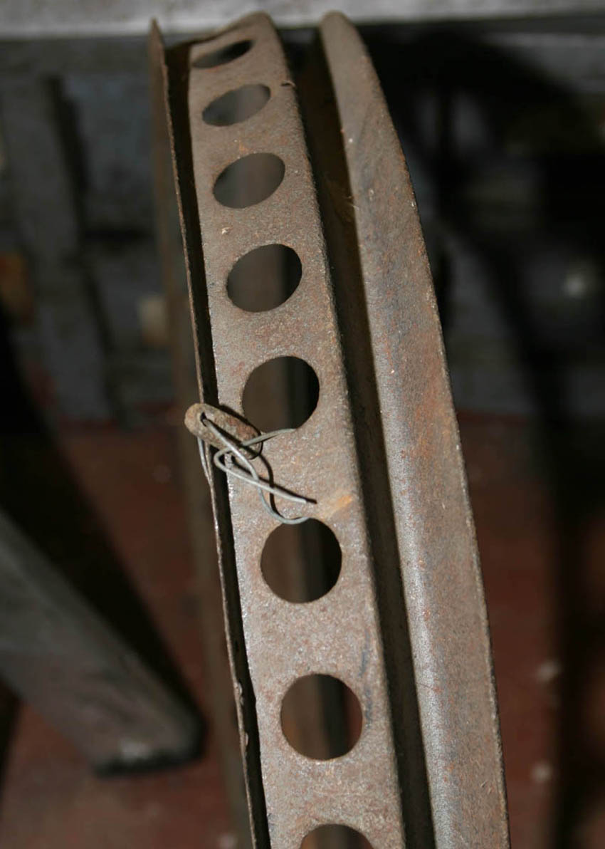
. . . And here is the corresponding rear wheel belt drive rim. Again, I belive this to be an original early Douglas 2 3/4hp item, looking identical in diameter and profile to other Douglas belt rims.
The rim did have a lot of heavy pitting, and visually at this stage did not look that good. However, when holding the rim and pressing the steel, it was clear there was still a lot of strength.
Ultimately, when later restoring this belt rim, I decided the best course of action to maintain that strength would be to reduce as much loose rust as possible with a rotary wire brush, then chemically treat to ensure it does not get worse - but not to try and rub down the metal any further.
Instead I built up the paint with Primer/Filler two pack, multiple coats, and did not worry too much about rubbing it down, just a light rubbing, which seems to have worked quite well. Again, I will cover this in a later wheel building article.
Note also that the previous owner had thoughtfully wired one small original plate to the rim. On inspection I could see the plate had two threaded holes and these holes coincided with matching holes around the circumference of the rim - clearly these plates were designed to fit around a spoke and two small screws through both to retain rim to wheel. Again, more on these later
Original early type 2 3/4hp model belt drive pulley, looking a bit sorry for itself. However having found out a bit more about this model - I can see there was another type fitted slightly later, while this was the earlier type - fitted to the pre-war racing models, which is what I wanted my build to be based on.
The pulley is actually in two parts and is variable - i.e. by unscrewing the outer rim from the inner, the belt drops in the pulley lowering the gear.
Deep groove are visible in the rear pulley half here, as well as a few traces of the original nickel plating.
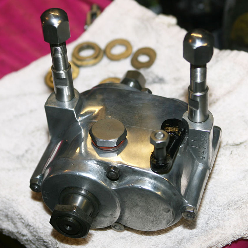
Like a gearbox, only smaller . . . !
This dinky little item is actually a two speed gearbox, and I gather was quite an advance feature when first introduced - the majority of bikes at the time being single speed. I am not sure exactly, but think this type of gearbox was first introduced in approximately 1911 and continued right up until the early 1920's, by which time I would imagine it was very much the economy spec model - a three speed gearbox and clutch model being the norm.
Again, for my model - although my frame is 1920, as I was wanting to build a TT Rep of the earlier pre WWI racing models, this was the gearbox that would have been fitted, rather than a three speed. This photo was taken before any stripdown, but overall condition looked good and no visible play on shafts
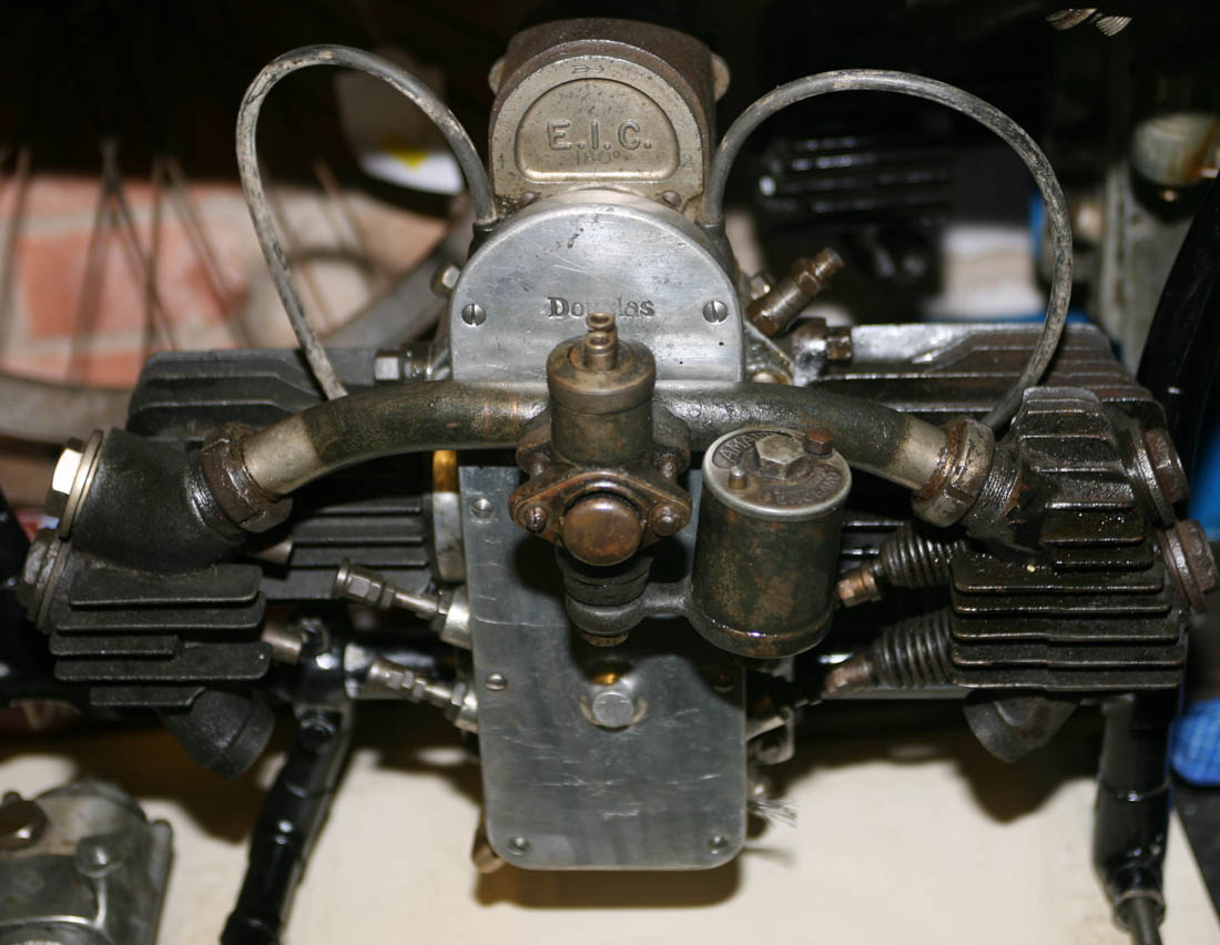
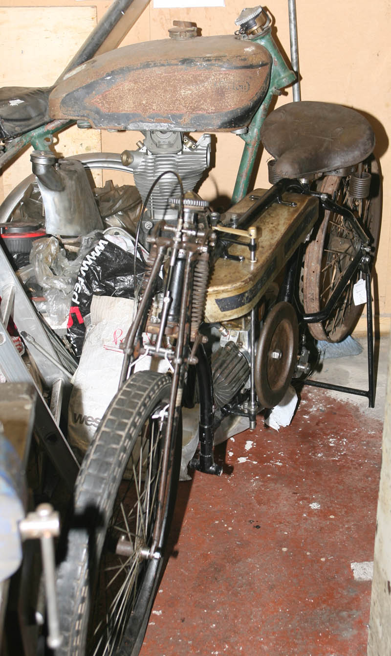
Here is the engine unit as purchased, I have just loosely aseembled some of the parts that came with it. Like the frame, the engine has a number that equates to 1920 - although as far as I know the differences were only minor from the models run of 1911 - 1923'ish. However, if you look carefully you will see the barrel on the left has less fins than the barrel on the right - indicating it is the earlier type (not sure, but think the extra finning came around 1916?).
Magneto is EIC and would have been the original fitting in 1920. Earlier pre WWI models would have been more likely fitted with a Bosch magneto - but for obvious reasons they were no longer available once WWI started
Inlet manifold and early Amac carburettor are wonderful time capsule items. The carburettor is correct for this model and is lovely and original - it looks to still have the original nickel plating on it - click on photo to see a larger picture in more detail.
However, what is most interesting is that it still has traces of dark Khaki paint - which I believe of the shade used by armed forces in WWI (I have a small original army WWI toolbox in the same shade). As 25,000 Douglas 2 3/4hp models were eventually produced for the British armed forces - I am wondering if this carb and manifold could have come off one of those WWI army models? Given that the Bonhams collection of Douglas's seem to have come from a very serious Douglas collector (whom I assume had passed away), and there were so many other time capsule items in amongst the lots - this could have sat untouched in his collection for many years. This presents me with a bit of a dilemna - because it definitely needs stripping and some parts need work, but I am not sure I want to remove what could be possibly original WWI paint.
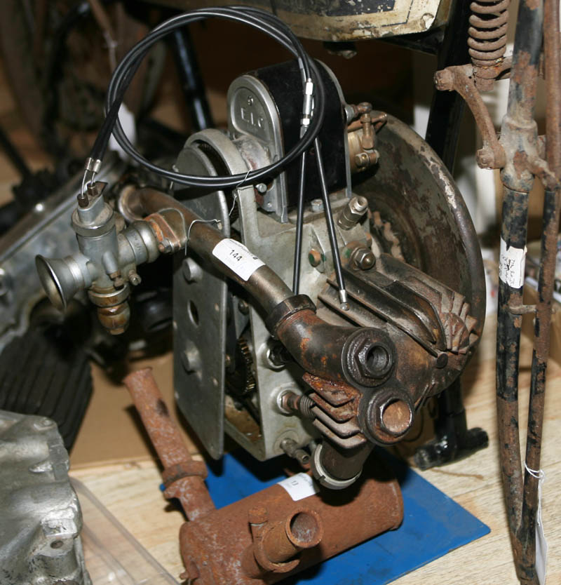
As I mentioned in my first article on the Douglas - while at the Bonhams auction, I stayed right to the bitter end of the 4 hour auction - because I had noticed a poor photograph of what looked to be another Douglas 2 3/4hp engine on its own. I was lucky enough to purchase this for a very reasonable sum - with no other bids placed on it other than my own. I assume by that late time in the afternoon the other Douglas bidders had long gone - there having been an approx 2 hour gap since the main Douglas collection had finished!
This was the second engine, still mounted on its own blue engine stand, on the kitchen floor on the evening I purchased it, surrounded by the other Douglas parts. As can be seen, it looks to be mostly complete - although fitted with what looks to be a much later type Amal carburettor. As well as providing me a spar engine for the future, it also has another EIC magneto, and many smaller items - in case my main engine was missing anything. If you look carefully you will see it has a flywheel fitted - one of the items missing from my main purchase, but shortly after this time I was able to purchase a second early type flywheel off Ebay. Most usefully - this engine was also fitted with 'odd' barrels - but reversed from the main engine . . . so they could be swopped round - how lucky was that! When I checked the number, I found this engine to be a very late one, dating to 1923
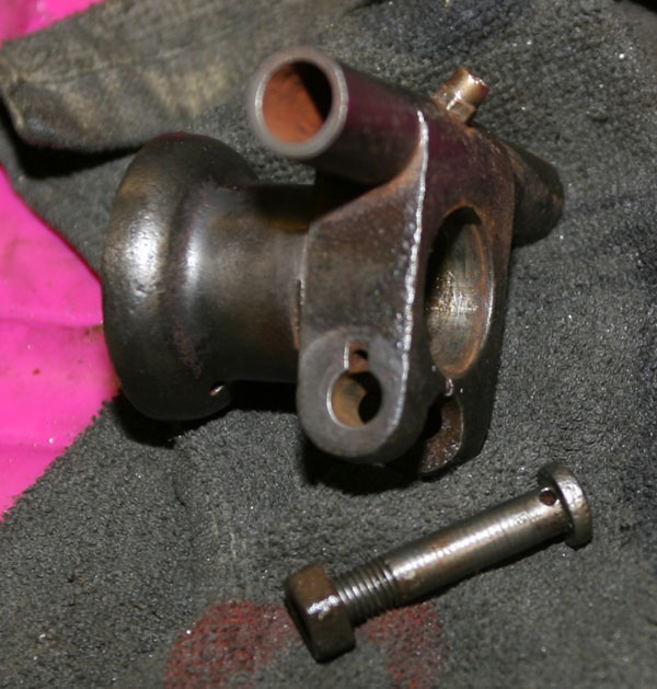
Rear subframe bolt had definitely seen better days, but looks like it had been fitted for many years - as the line of pitting in the centre seems in line with frame lug. I quickly replicated this in stainless steel, but checking the spare parts catalog much later - realised that a curved head bolt, with pin - like the front fork Head Clip (shown earlier) was original fitting. No matter, mine looks nice so I think will stay! Not why this bolt looked so bad though, a the frame itself looked in good original condition - although I could see the previous owner does seem to have already restored that at some point in the past
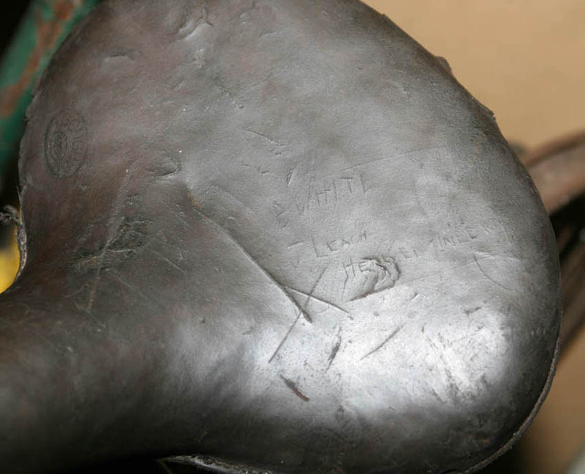
Saddle that came with bike was yet another original and interesting part that - after some work, yielded more history than was initially obvious.
As it came, it was complete and in reasonable condition underneath - but the leather looked very tired and dried out on top, and not really usable. I was thinking I could save the base but would have no option but to get the top half recovered - as most Edwardian rebuilds seem to have.
However, over the coming weeks, every time I went into the workshop I gave it a another soaking in saddle soap, until eventually is became more supple and regained some of its colour and a lovely patina.
In the top left corner you can now see the makers mark appearing - it is a Gough, which I gather was a Birmingham based saddle maker - one of many popular makes of the Victorian and early Edwardian period.
But what I found really interesting was what started to appear on the centre section - what I thought was originally just a collection of bad scratch marks from many years of ill use . . . but what became apparant was that at some point, someone seems to have scratched a rough square in the top, and within that square, just legible, are the names B. White and J. Leach. Underneath that, are two words. Unfortunately the first word has some scuffing over it and is pretty much illegible, but having closely examined the second word it looks to read 'Engineers'. I cannot be sure - but it is very poignant to think this may be another WWI WD artifact, and they are the name's of two British soldiers from
one of the Engineers battalions (i.e. Royal Engineers) that shared this bike as dispatch riders?. I guess I will never know for sure - but like most people, I have a special respect for those that served in the first and second world wars (indeed my Grandma's father was killed at Paschendale in 1917 when she was only 12 years old - like so many other families of the time), so I will now do everything I can to keep this original cover - although it will need to go to a specialist saddle repairer to have the frayed leather around the stitching repaired
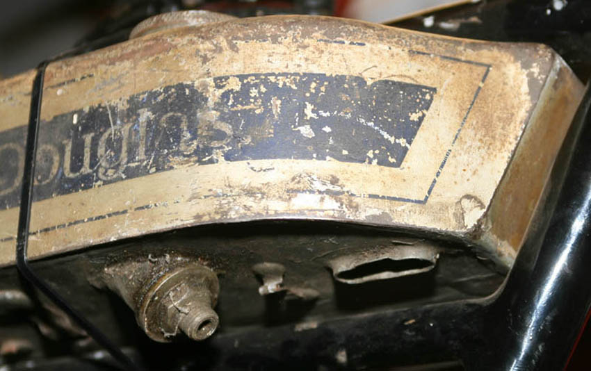
Petrol tank, as fitted for the auction (complete with nylon tie down strap, and just visible the cotton of the Bonhams tag), was definitely one of the gems of the Lot, and having closely inspected the other Douglas project kits being sold alongside it at the same time - was by far the best of the bunch.
As you can see, it looks to be in really nice weather worn condition - and I am pretty sure it is still the original paintwork - fantastic. Likewise
the filler caps and hand pump also look original and timeworn.
Initially this put me in a real dilemna, as I always feel the need to restore a petrol tank and paint/line it to a concours finish. However, having taking a straw poll from others that have seen it, I agree it would be a real shame to re-paint it, so I will do my best to sympathetically clean it and find a suitable satin lacquer to protect it for the future. in the intervening two years I have now also managed to acquire an earlier (1912) tank for my second project bike, and a lovely condition second tank of this style, already prepared in grey primer
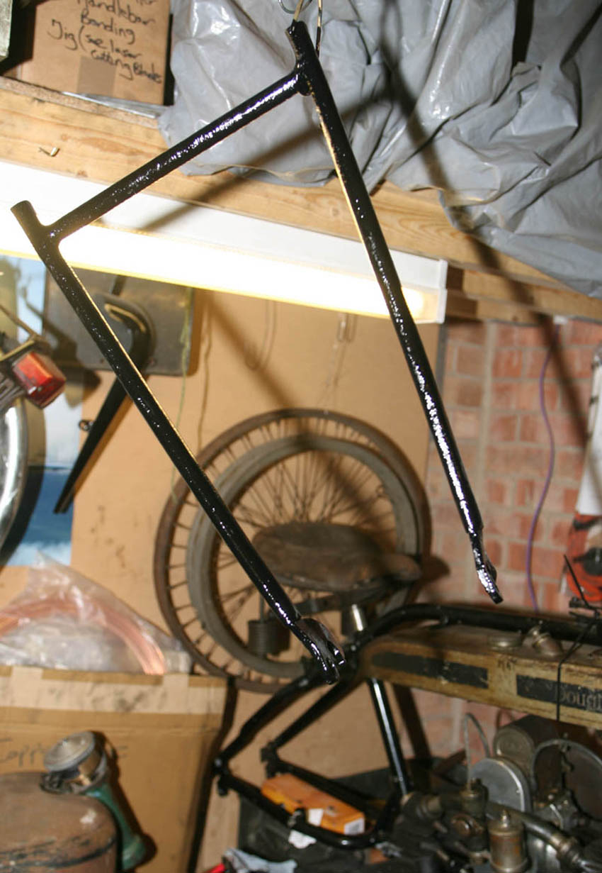
In the first couple of weeks after acquiring the Douglas kit, I needed to clear a space in the workshop to put it - as when I originally set out to the Bonhams auction, it was with the intention of purchasing a Vincent RFM, not buying another bike project! Here it is in the photo above a couple of days after getting it, having cleared a suitable space. At this stage, although a few parts are loosely assembled, there is clearly a big job ahead!
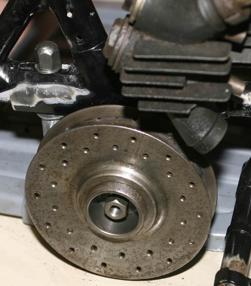
Jumping ahead a few months to the photo below, some of the first restoration tasks have been done and some of the missing parts made, and loosely assembled to get it onto its wheels for the first time.
First Restoration Task - Belt Pulley
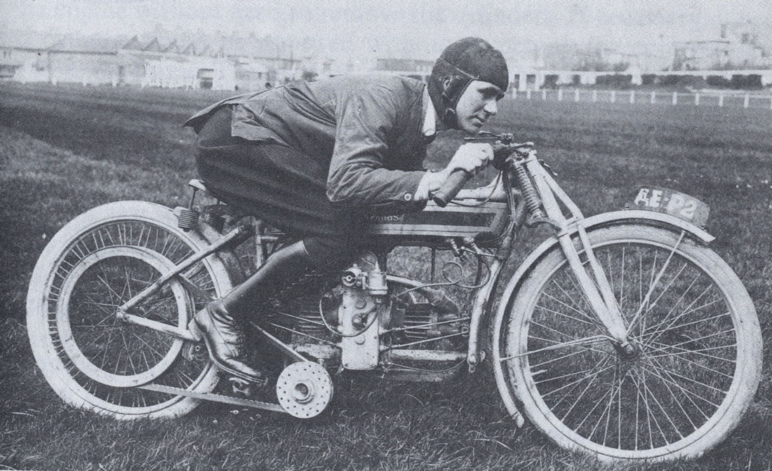
Great period shot of Alfie Alexander aboard one of the first Works OHV bikes at Weston Super Mare. Only a handful of these first Douglas OHV racing machines were made - for the 1913-1914 season, so I am guessing this is 1913. They used the crankcases of the 2 3/4hp SV model, unlike the first production OHV models made in 1920-21 which were very different all together. Unless anyone knows different - I dont believe any of this early OHV Douglas model survive.
But as you can see - the belt pulley fitted to this bike (as well as other pre WW1 racing bikes) was of the same type as the one that came with my project bike.
As a footnote . .. I am also collecting parts for a 2nd project bike, where I hope to replicate this 1914 OHV TT bike
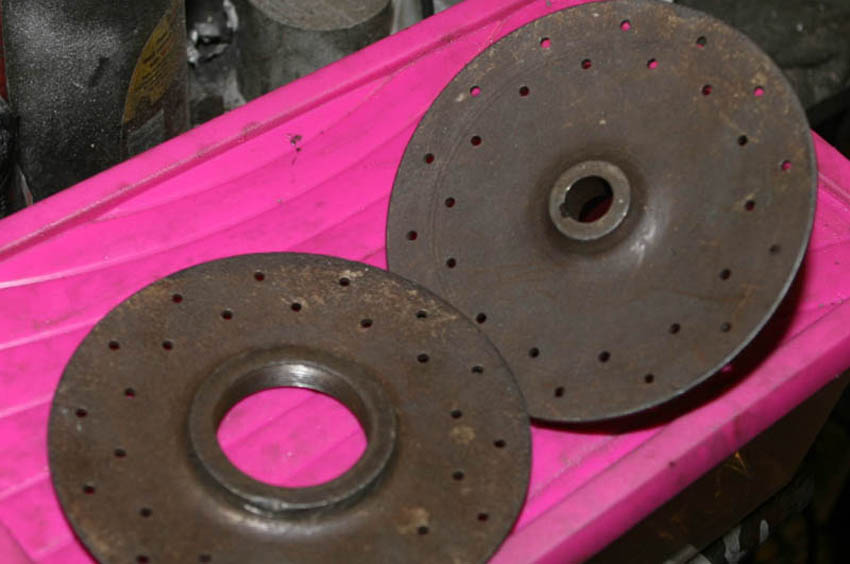
Here are my two pulley half's as they came from the auction. Basically sound, but as you can see from the lower photo - quite heavily worn where the belt fits - clearly they were of hardy stock in the old days and did high mileages!
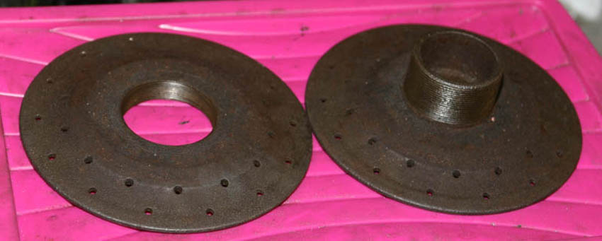
So, first step was to try and remove as much of the ridge as possible - without taking away any more metal than necessary.
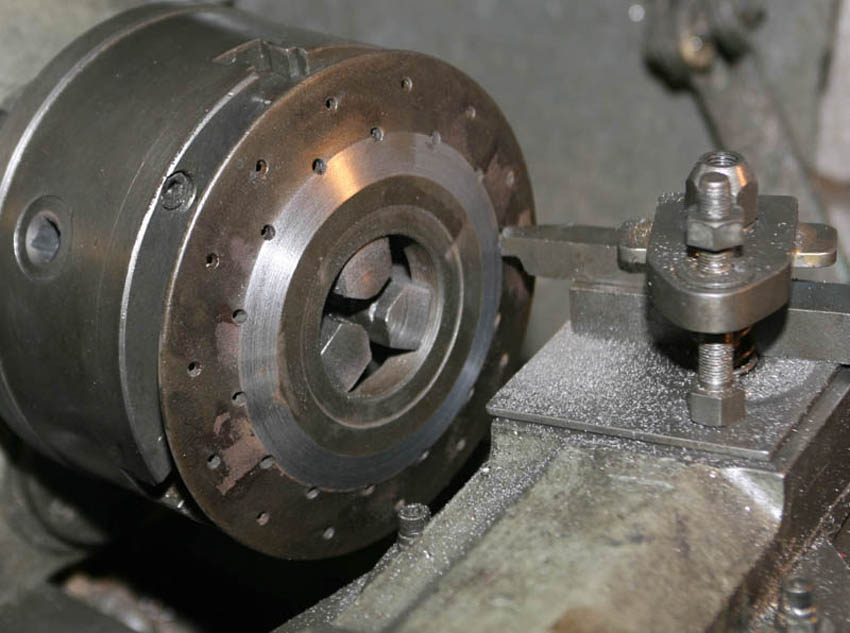
Here you can see the outer pulley rim mounted in my Smart and Brown lathe and I am gently skimming the worst of the ridge away. I repeated the process with the rear rim as well
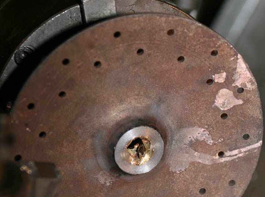
A more difficult issue was - when I offered the rear belt pulley up to the gearbox shaft taper - the belt pulley was wobbling around badly. Clearly the pulley had ran the latter part of its working life loose on the shaft and this had resulted in a lot of wear. As it was, it was unusable.
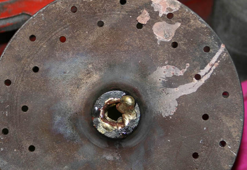
Therefore, having thought about it - as I have done with rare taper sprockets in the past, I decided to use Oxy Acetylene to butter the inner taper with braze, where it could then be machined. This is the rear after building up with braze
Admittedly, the pulley looks a bit of a mess at this stage! This is the front face of the rear pulley just after having bult up the braze. It was an easy job and because the pulley looked to be cast, and I was unsure what the original material was - I used lots of Pre and Post heat to ensure the pulley did not crack from heating up/cooling down too quickly. Although it looks a mess at thsi point, it actually buttered against the base metal reasonably well and was a success.
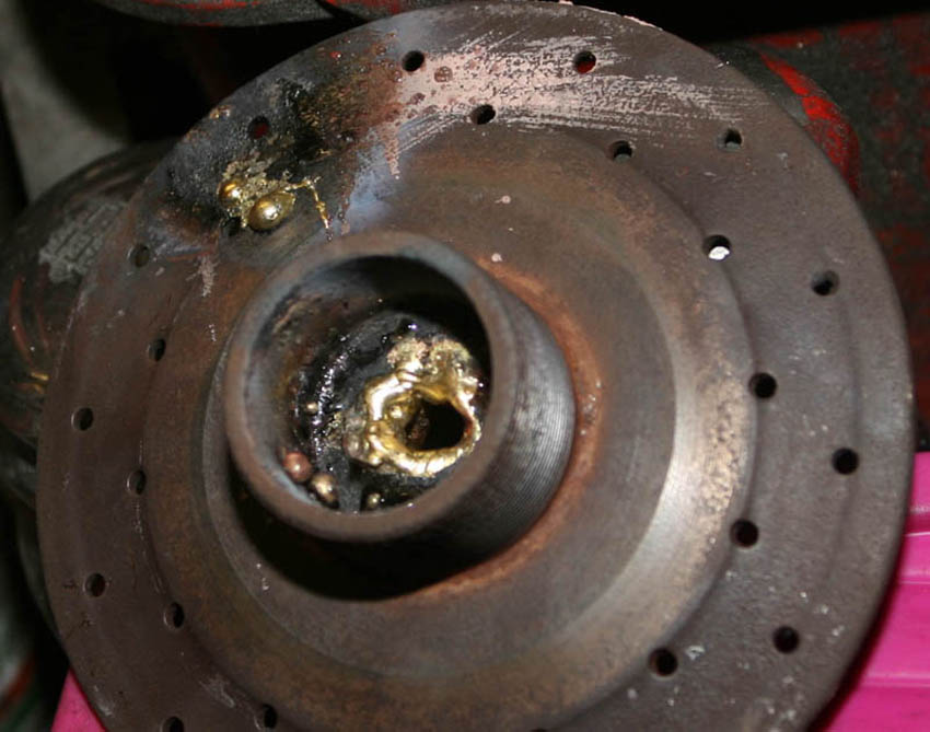
I did experiment with a particularly badly grroved area of the rim, to see if building up with braze may be an option - but gave up on this after the trial area in the top left of photo. I ended up just machining as much of the groove away as I dare
And here, starting to machine the excess braze away. Remember this is actualy the rear face, so I started by facing, then gently removing the braze away from the centre using a taper cut
As I got closer to the final taper dimensions I could see where the wear on the original taper was uneven and ragged. If I remember correctly, I also found a couple of minor areas where the braze had not reached and needed to reapply. Ultimately though, it worked well and I was able to restore the taper well enough for re-use - but a reminder I will need to regularly check it does not loosen again
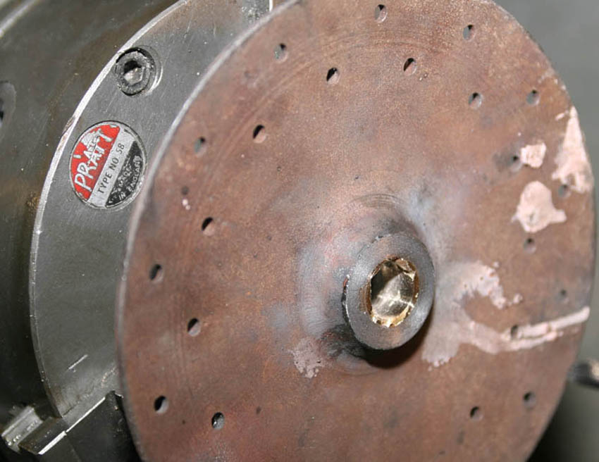
And here it is after all the work done - looking very different to how it did at the beginning. You can just see the inner lip of the rear pulley, which has also bee skimmed. After finishing the machinng of the taper I also skimmed the inner boss to to clean it up, made up new gearbox nut and cleaned up the thread. To h the front belt pully plate, as well as skimming the rear, I skimmed and re-chamfered the front locking face ready for locking ring (see next photo) and chamfered all the original rusty holes. The overall effect is strikingly different from how it started, and quite pleasing to the eye
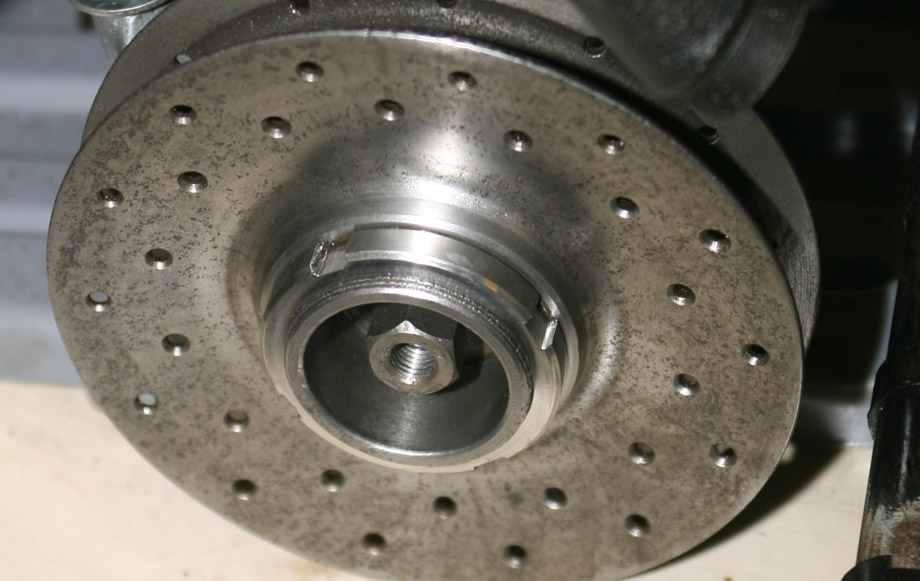
And finally - I machined up from stainless steel a pulley lock ring - as shown here. As you can see - by using a C-Spanner, this allows for the lock ring to be loosened, the pulley to be adjusted in or out and then lock ring tightened, allowing gearing to be changed on the road. I was tempted to leave the pulley looking like this - but knew it would soon rust again in use, so later had the whole assembly nickel plated
Some Period Photos - Douglas 2 3/4hp models being raced:
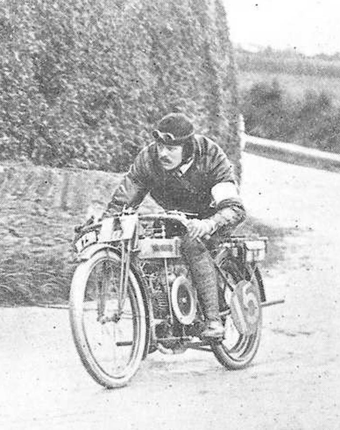
Works rider Harry Bashall at the 1912 French Grand Prix. I believe this was shortly after he had won the 1912 Junior TT on the same bike at the Isle of Man. you can see this Works bike has many small variations from the roadgoing models of the time - i.e. a special straight through exhaust, extra large oiling pump and possibly extra finning to the cylinder heads (as was used on roadgoing models in later years)
Another good photo for showing some of the detail of the early race bikes - this one I think was Les Bailey at Brooklands .
Again, it shows the special exhaust system fitted to the Douglas race bikes - very different to those fitted to roadgoing models - which used a cylindrical collector box under the engine. This photo also gives a good
view of the large external oil pump that seems to have been fitted to the early Works racers. I have been keeping an eye out for one of these on Ebay for some time - for my second bike, for which I have an earlier 1912 tank like this one - but so far, to no avail!
I have tried to make out what is fitted in front of the belt pulley but cannot work it out. I can also see a special type of twin barrel carburettor is fitted, I have not been able to identify what make it is though
Les Bailey again at Brooklands - I believe this was also 1912 where he won the Junior GP. Notice the front forks at this stage had straight links, rather than the curved links which shortly followed. Also no mudguards (although this was probably just because it is Brooklands - they seem to be fitted on racers for most road races. Other point of note is that the on these Works bikes, the front down tube has been chopped after the engine rail tube. On roadgoing bikes, this tube continued to allow for another crosstube to hold forward pegs/footboards.
I cannot bring myself to do this to my frame!, instead I will probably make little alloy castings to hold spare spark plugs which I once saw done many years ago
All I have against this photo is J. Haslam, who was a well known pre WW1 Douglas rider and one of the 1912 Works TT team. Therefore assume this photo may habe been taken at the 1912 Junior TT or a race of similar period. Note TT style handlebars, but in this case front footpeg mounting bar seems to have been retained.
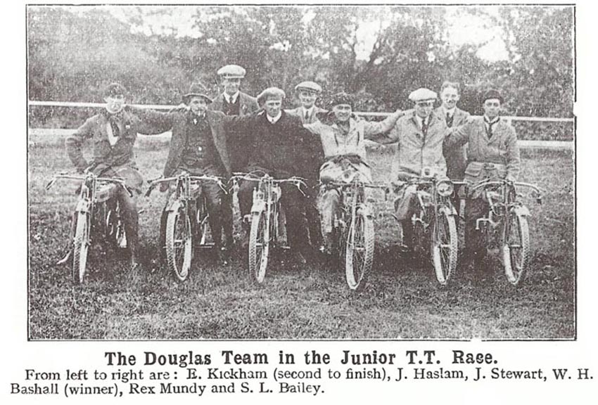
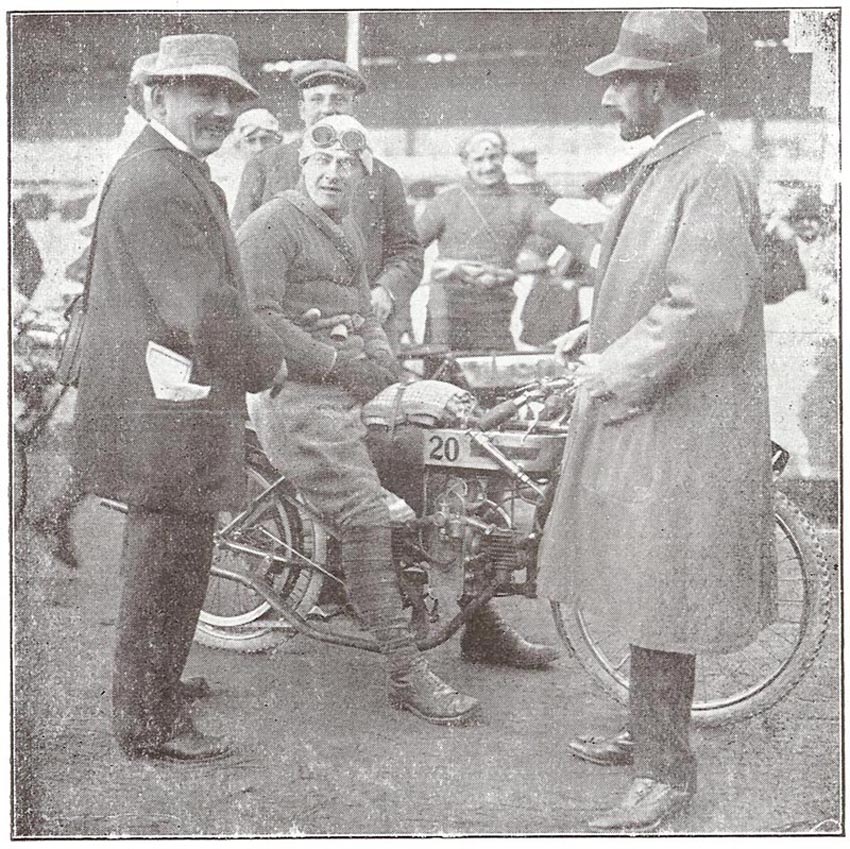
The caption says it all - other than it was the 1912 TT and at that time Douglas were one of the most succesful 350cc (2 3/4 hp rating) competitors in the class.
I am not sure if all the riders were employed as Douglas professional riders on Works bikes, or if some were privateers on their own bikes?
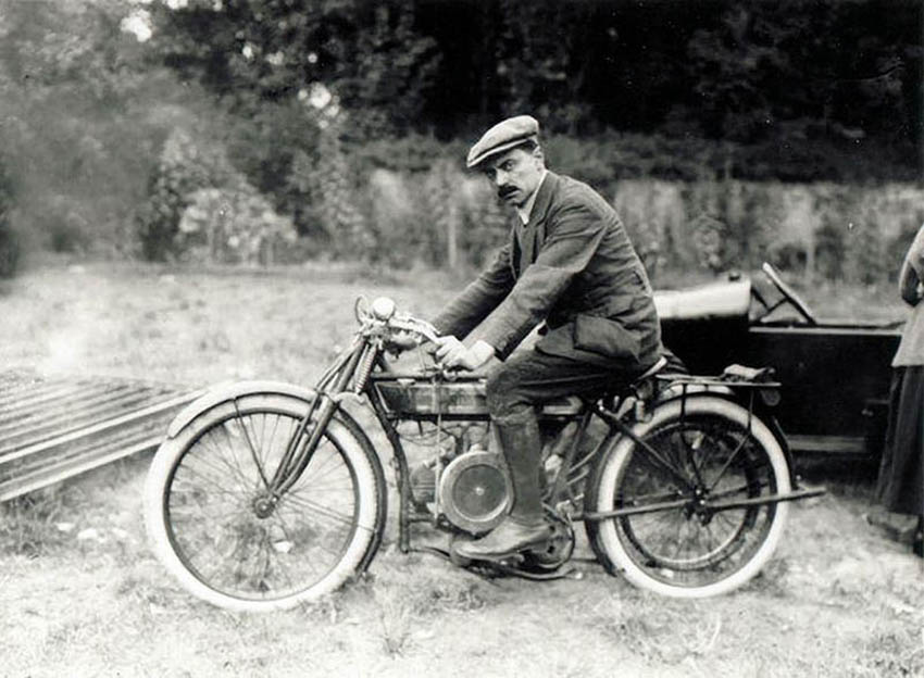
I don't know too much about this photo, but it is likely to be a gentleman on a sports spec Douglas 2 3/4hp model rather than an out and out racer. I would estimate from the car in the background it is late 19'teens or early 1920's - but bike looks pre 1920 and I notice from reading period magazines that occasional reference to TT Rep spec is made - although this may relate to the handlebar shape. Not sure but this looks like a sporty version of the model
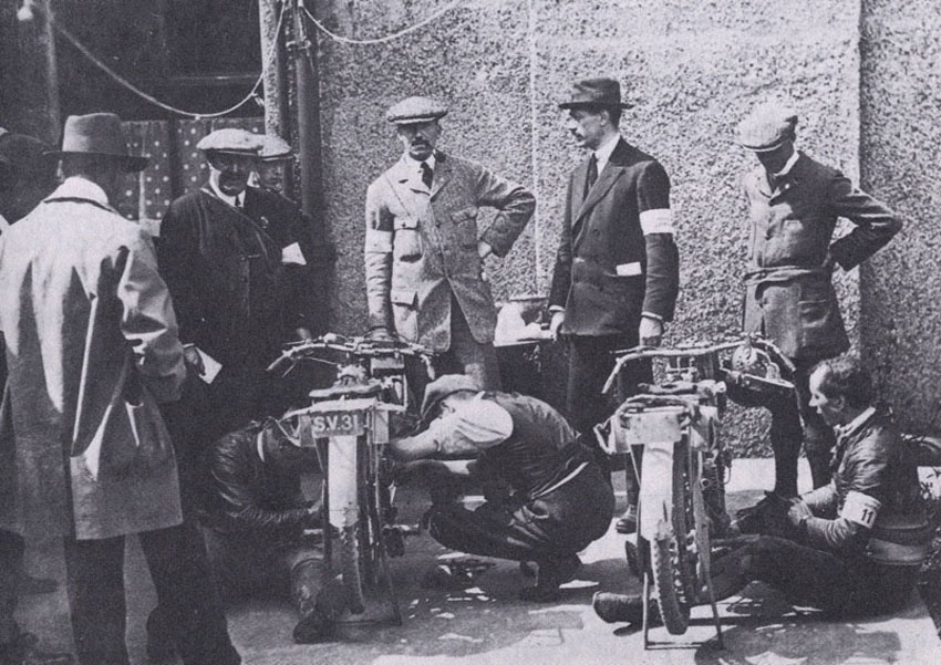
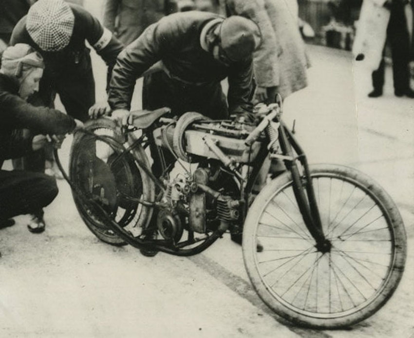
I believe this photo was also at the 1912 TT and shows Harry Bashalls winning Douglas on the left - assume being stripped for inspection by officials after the race. lovely view of the racing handlebars and it was this photo that gave me a bit of useful information that the Works bikes seems to have had special handlebars fitted that look to have clamped to the fork crown just below the top spindle. On production models at this time - the norm seemed to have been push bike style handlebars with a vertical stem that pushed down into the steering column. In my next article I will cover how I tried to replicate this style of handlebars, I much bigger job than I originally thought it would be
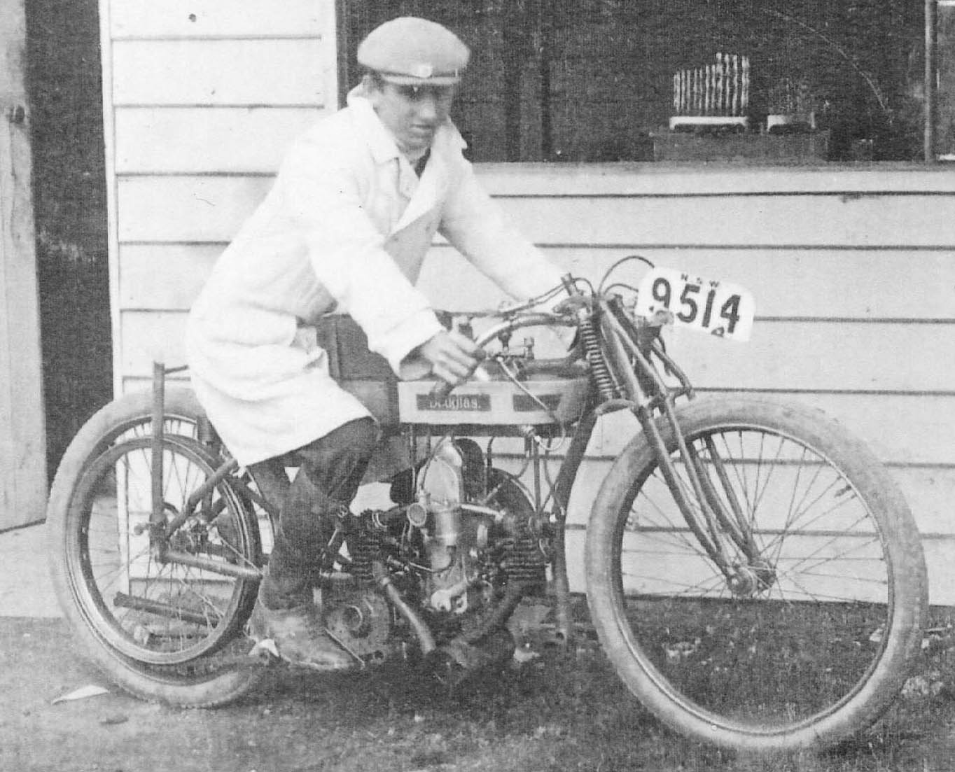
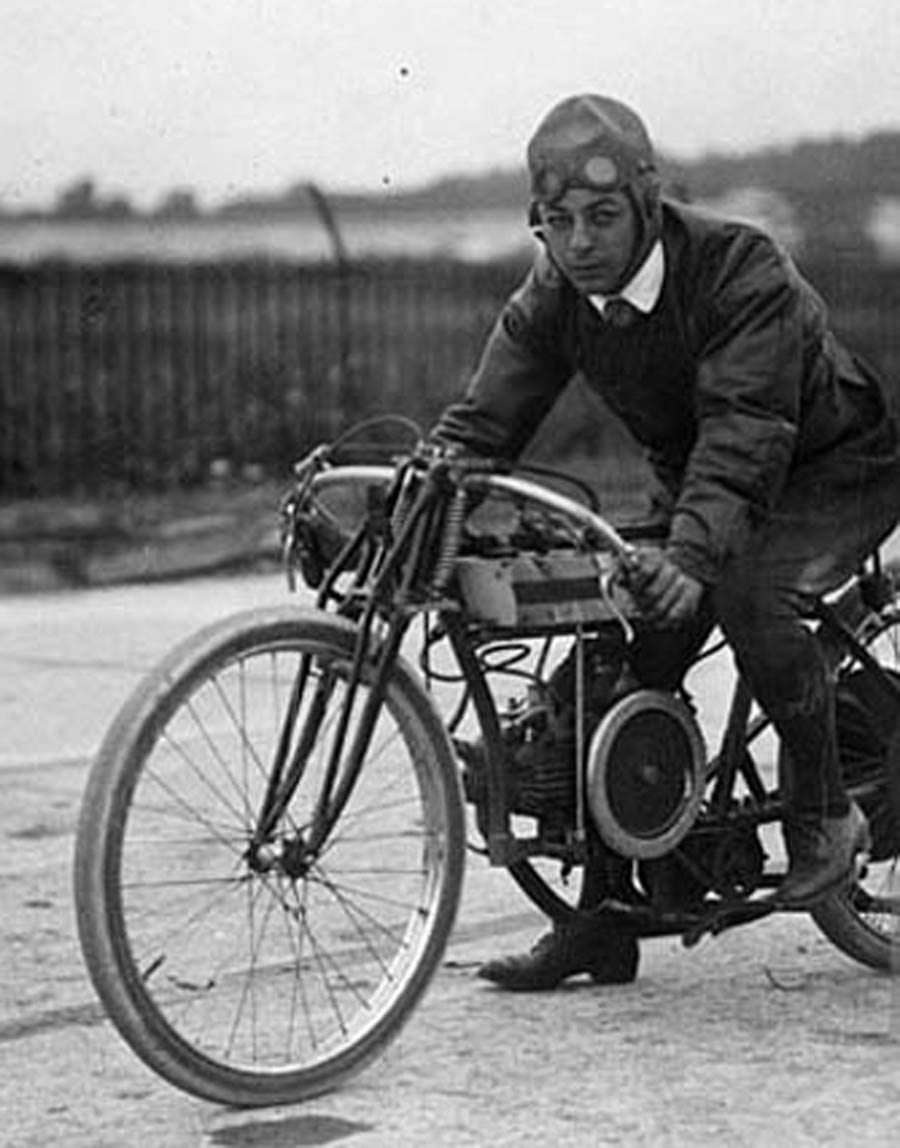
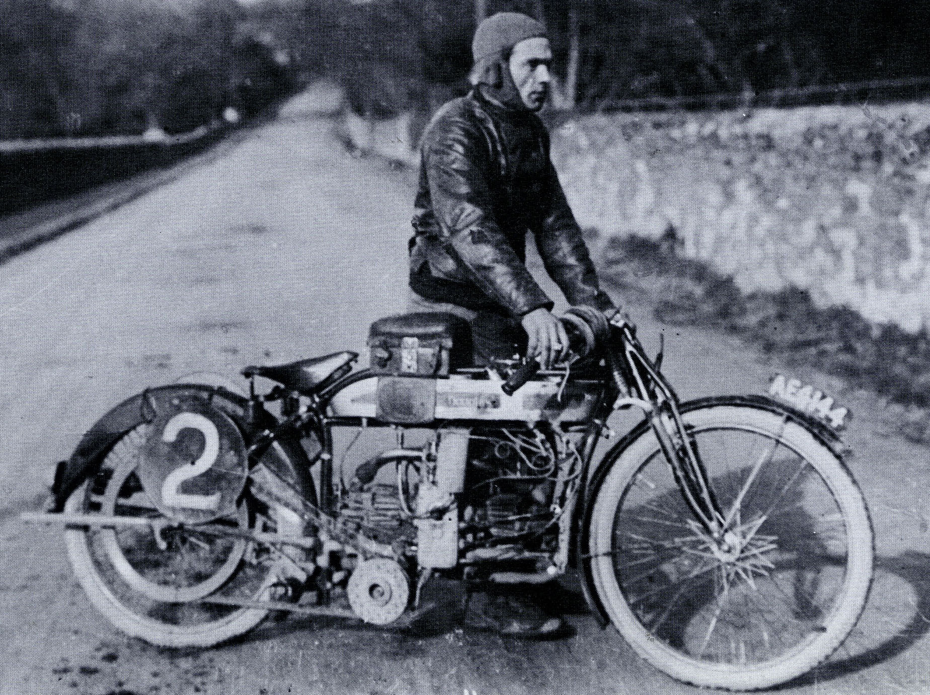
All I have about this photo is that the rider was called Frank Mellor. However, the front number plate seems to indicate that the location is New South Wales - Australia, where I gather Douglas's were also popular. It is hard to tell if this bike is a purpose built racer, or just a stripped roadgoing model (notice roadgoing silencer fitted) - but certainly looks purposeful - and again, Works style racing handlebars look to have been fitted
Another photo of Harry Bashall in the sucessful 1912 season, this one I believe to be from the 1912 French GP. The gent in the white jacked is Willie Douglas himself. I assume the bike is the same bike that won the Junior TT
And this is one of my favourite period photographs - it showing W Thornhill on one of the first 350 OHV Works Douglas's entered for the 1914 TT. However, these bikes were not as succesful as the SV racer's were in 1912 and I gather this particular bike did not finish. When comparing this to the SV 2 3/4hp model, you can see that although they both use the same style of crankcase there are a multitude of other differences. I would love to know if any of these OHV race bikes survived?
Next Restoration Tasks - Fastenings, Gearbox and Oil Pump Sight Feed
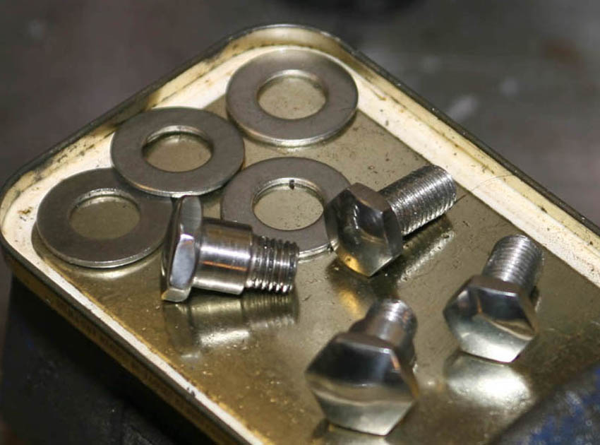
It quickly became apparant that to even allow me to loosely assemble large lumps of my Douglas 'kit', I would to need some of the missing fasteners. I made the decision very early that I would make as many missing parts myself from stainless steel - this not looking too disimilar from period nickel plating once polished. I tried to get general shape from any bolts I did have, as well as looking at photos of other restored bikes - but may have not got all head shapes correct. In this case, here are bolts for fixing the rear subframe to the rear wheel frame tubes and the rear stand bolts - so I could assemble the bike on its own rear stand
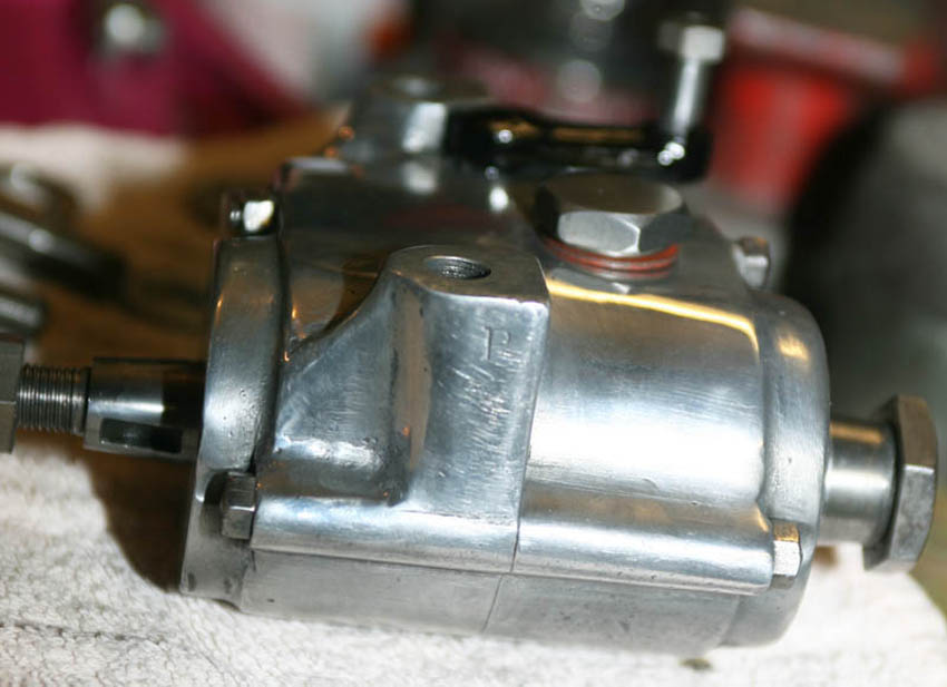
The little 2 speed gearbox looked in overall very good condition but was a bit grubby and had no mounting bolts fitted. Because it felt like the bearings were good and the selector fork to move it from Low/Neutral/High worked well and had no slop - I concluded it had probably already been stribbed and rebuilt at some point. Therefore, for the moment I decided to clean it up cosmetically only, and make mounting bolts to the frame. I would then come back and re-visit it before final assembly (which is actually what I did far more recently in 2019 - i am pleased to say all did indeed look good and no further work needed.
But when this photo taken I had finished cleaning and giving it a light buff (previous owner I think had given it some polishing as part of restore) and cleaned up fastenings. Note the 'P' stamped on side - not sure what that means, but there are a few nice period style digits on the gearbox and crankcase castings
I was flying blind when I made up these studs - I had very little to go on, on what the original studs to secure the gearbox to the frame would have looked like. So after measuring the holes in the frame, and making sure I left as little room for sideways play as possible - I machined these studs which are shouldered in the middle, both ends being of a lesser diameter. Obviously one end is threaded to screw into the gearbox, and I milled flats in the middle to allow the studs to be tightened. I then made up some nice domed crown nuts to finish the job, again in stainless steel. The length of the studs allow for thick spacers above and below the frame, to keep things good and level . Note gearbox number on right hand lug, again, indicating a 1920 year number
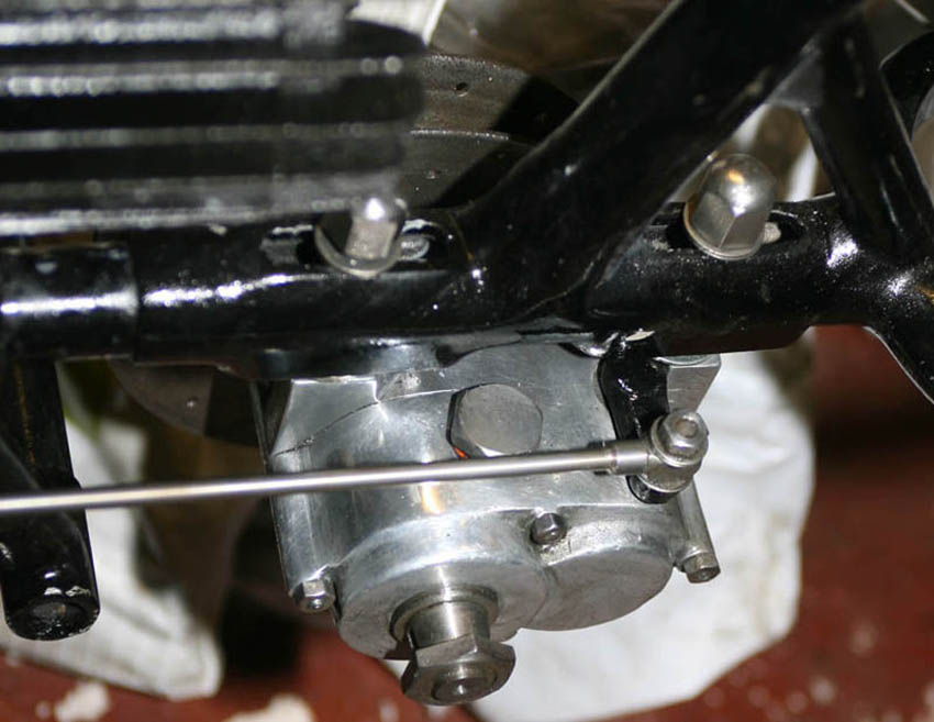
Trial fitting of gearbox to frame, showing large spacer washers and domed nuts. I subsequently found through looking at other 2 3/4hp models that the original style nuts I have seen so far do not look to be domed - and also do not look as nice . . . so think I will keep these as is. I am not sure - but dont think the gearbox fille nut is correct - it looks a bit big, and since this photo I have acquired a couple more 2 speed gearbox's and they have a smaller brass filler insted. No matter, I am not trying to be perfectionist with this build - just doing something I like and I quite like this big nut, not much chance of rounding it, providing I use the right size spanner!
The frame at this point looks fully painted and finished - which the previous owner had already done - but it had lots of chips and blemishes, so eventually in 2018 I ended up rubbing down all the frame and subrframe and respraying in primer and then black 2-pack
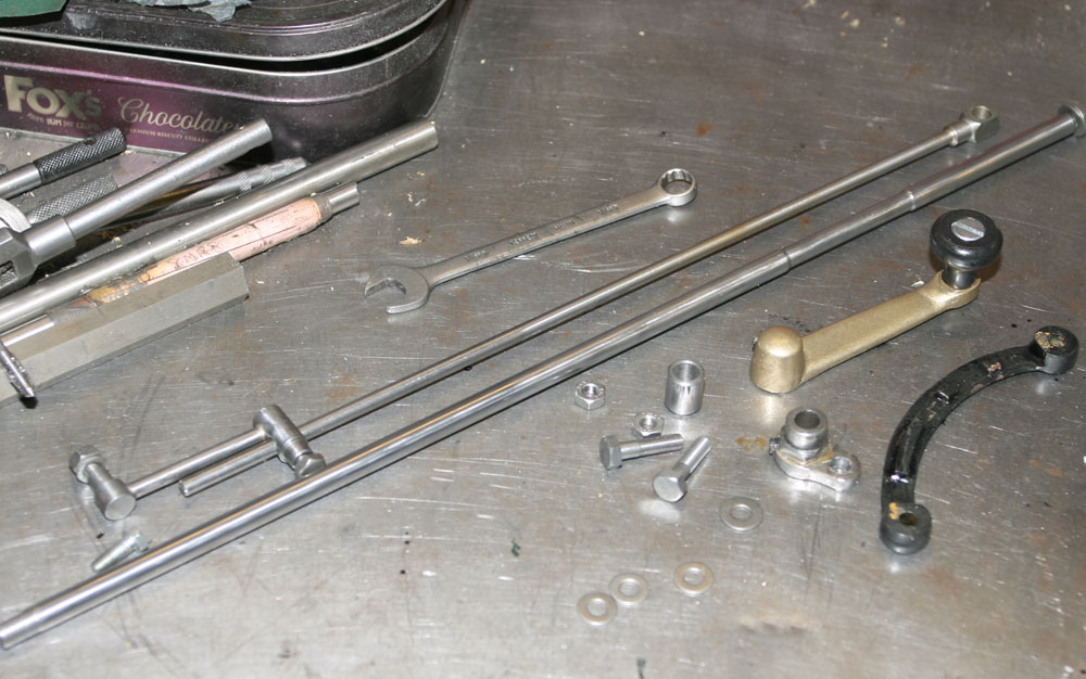
As the frame came from the auction, it was fitted with a gearchange 'gate' on the tank top frame tube intended for a three speed gearbox - both 2 and 3 speed box's being offered for the 1920 production year. As I had a 2 speed gearbox and intended to fit that - I needed to find the tank top gate intended for that earlier 2 speed model - which I quickly found was a bronze casting with High/Low cast into it, and - understandably, very difficult to find! Also, the distinctive Douglas gear lever was missing from the project kit. After a long time hunting, I found Bert Poll's excellent website in Holland:
https://www.bertpol-vintagemotorcycles.com/GB%202.htm
From Bert's site I was able to buy a very good copy of the original type gearlever, shown here. I then ended up making most of the missing gearchange leverage shown in the photos here. I also managed to purchase off ebay an original 2 3/4hp gearchange rod in very rough condition. From this I was able to replicate it on my CNC lathe, and so I ended up writing the programs to be able to make this and offer it for sale on a new Douglas section of our own online website:
https://racingnorton.co.uk/epages/4c675e64-813f-4c0a-8926-87a680c962a0.sf/en_GB/?ObjectPath=/Shops/4c675e64-813f-4c0a-8926-87a680c962a0/Categories/Items/8_Douglas_2_34hp_Parts
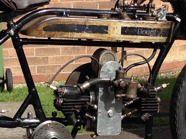
And jumping ahead a bit in the build - eventually I ended up with 2 of the earlier bronze/brass 2 speed gates. The first one (fitted to the frame here with the original barrel type screws at the time the photo was taken (I have subsequently replicated them in stainless steel, and also offer them from our Douglas catalog), came from a whole 1917 donor chassis I saw offered on E-Bay in 2017.
It sounds a bit extreme to buy a whole chassis just to get hold of a gearchange gate - but although in extremely poor condition, the frame had all the castings/lugs I needed to later consider a second OHV replica. Then, shortly after the fiirst 2-speed gate came along, just like a bus - another Douglas enthusiast contacted me via the Dougals Forum website who had a 2-speed gate but needed a 3-speed version . . . hence a good swap and the second one shown in the photo, for the future second build
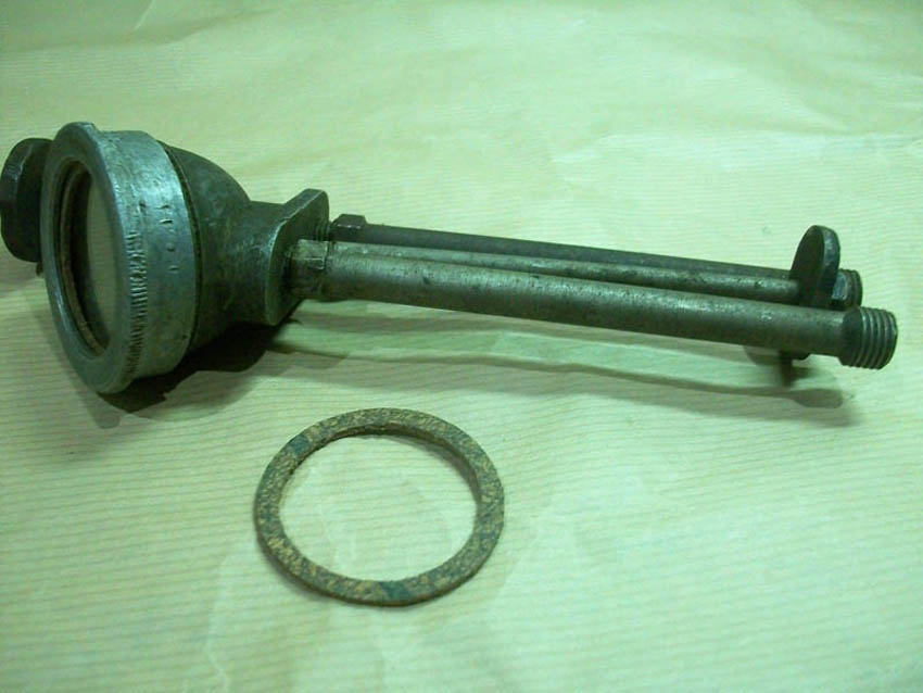
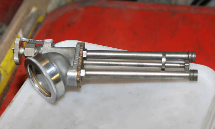
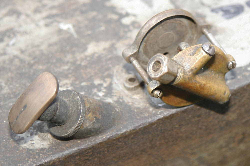
Back in late 2016 I found this while hunting E-Bay. It is a tanktop oil pump drip feed unit, of the type fitted to douglas 2 3/4hp models after 1919.
It came as a basically all complete unit, but in unrestored and dirty condition. But at least it had a new cork gasket for the glass!
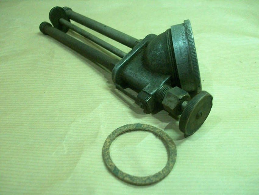
You can see in thei photograph some of the design and condition flaws.
It consists of an input tube, from the hand pump, a dial adjuster and site glass to show how much feed you are giving to the engine, and then finally an output feed to the engine. Between the input and output feed pipes is a retaining bolt and retaining plate - so that these can be fed and held through the petrol flat tank.
Note in this photograph the original site glass bezel is quite badly marked and the oil adjuster dial has definitely seen better days. Also, although present, the adjuster dial 'stop pin' has been screwed facing downwards, instead of upwards against the knurl of the dial
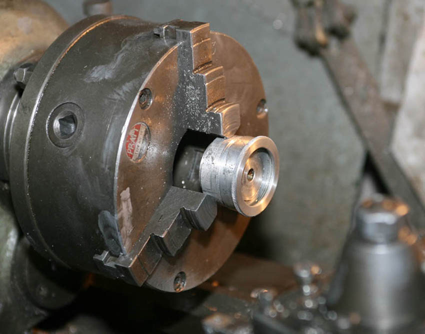
So first job was to machine a male thread onto a scrap of alloy bar, so I could hold the original alloy glass bezel true in a lathe chuck. Then it was easy to lightly machine out the worst of the knocks and bangs it had acquired over the years. I left the outer knurl in original pattern. The result was a transformation and greatly improved the whole look of the finished assembly
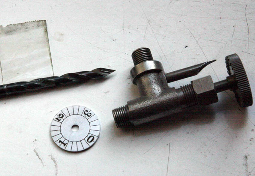
As it happens - I have already manufactured 'Best and Lloyd' style oil taps - of the type used to oil primary and rear chain from the wrapround oil tanks on 1930's Racing Norton singles. As can be seen in the photo of one of these - part ot their construction is a stainless steel lasercut disc with the same type face as would have been used on the Douglas hand pump aduster, and we also manufacture a very similar brass adjuster dial and shaft as the one fitted to the hand pump, with recess to take the lasercut disk
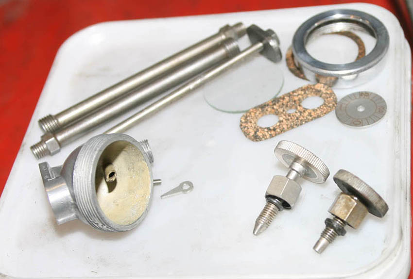
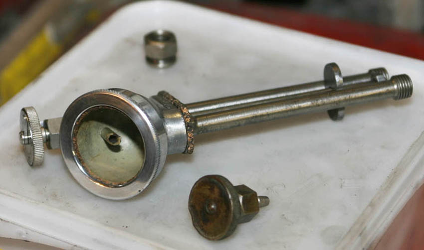
Here you can see the full assembly of parts just before reassembly. The main aluminium body/bowl was also made of a light alloy and cleaned up really well - including the original cast writing on the outside. Most pleasing of this item was that it still had present its original Ochre paint on the inside - which wll be clearly visible in use. You can the original adjuster dial on the right in this photograph, and my newly manufactured type on the left (they are dull nickel plated after manufacture) - it clearly shows that the old original adjuster would have been of little use, because it had been shortened over the years and the wrong taper put on its end, something I have seen numerous times on old dials - negating any proper adjustment. I used my special drill/taper mill shown in previouis photograph to restore correct taper in the main alloy body as well - so this one should work again as designed
As well as the mechanicals, I also fitted new glass - one of which came with this one and a couple of incomplete similar Lots I purchased from the same seller on Ebay. New cork gaskets, all original steel parts de-rusted and the dial spring replaced in the correct position as can just be seen in the top left of the photo here.
Final touch was to replace the missing pointer fitted to the dial of Best and Lloyd oil dials - again, another item I have had re-laser cut for my own oil adjusters, and just visible next to the bowl assembly in the photo on the left
The finished unit reassembled and ready for fitting to the Douglas petrol tank. You can also see the old dial here, which was replaced

And final picture of oil adjuster unit fitted to the tank, for which it was designed - and looking really good. This type of visible oil feed was the second type fitted to Douglas 2 3/4hp models - I believe from approx 1918-19, when the petrol tank shape changed to a slightly larger and wider shape.
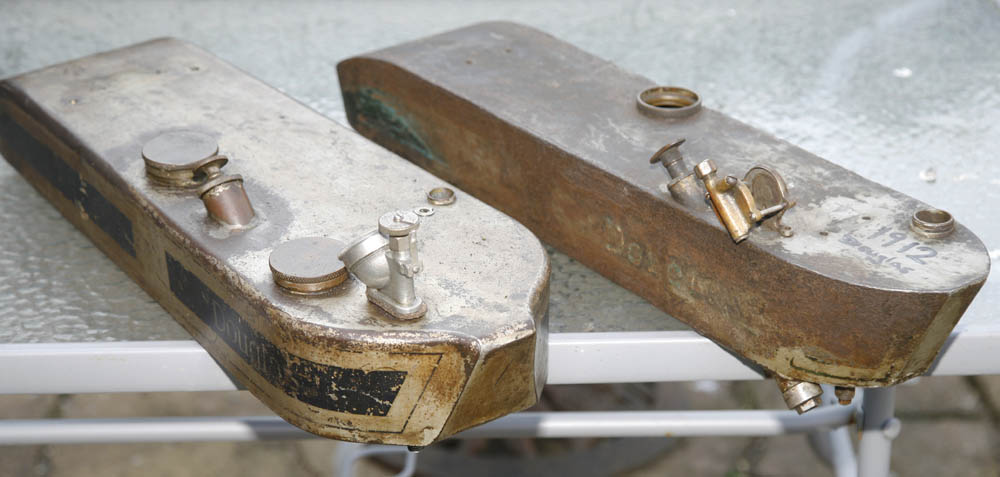
Jumping ahead a couple of years from when I first restored the oil adjuster assembly, are these photos of early and late type Douglas petrol tanks together. About a year after purchasing the first bike I started to accumulate parts for a future second Douglas build. I was fortunate enough to purchase a very early 1912 type tank from Bert Pol in Holland, shown here on the right in the top photo. As you can see, looking at both tanks side by side - the later tank is considerably wider and different in shape. Filler caps are bigger and moved from left to right side, and the hand pump of the later tank is a slightly wider bore. I think the later tank came in at the same time the frame changed - which was approximately 1919. I think this later style tank was very similar on most models through to the mid 1920's. As you can see both of these tanks are very original - although the 1912 tank will need some work on the other side, as one of the seams has rusted through. I have a 1917 frame for this to go with. I have also now acquired a second later tank already restored and in primer - as a spare
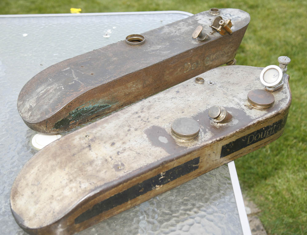
A close up of the hand pump and oil adjustment units on the earlier 1912 tank, as a comparison to the similar units on the 1919-20 type above - both very different. On the earlier style tank the hand pump was of slightly smaller bore. This pump looks original, although will need work. I thought at first it had been modified over the years - but now I am not so sure, it looks like the filleted pump handle may be original. I you look closely you will also see what looks to be an arrow stamped on the top - which looks like it might be original.
The oil adjustment unit shown here was another Ebay purchase - and being of a very rare type, cost me quite a lot of money, particularly considering it is quite incomplete. As you can see - rather than a screw on sight glass, which the later type employed - this earlier type was to brass/bronze castings, designed to have a cylindrical length of hollow glass in the middle, allowing the rider to clearly see the oil dripping. As you can see the glass was missing from this unit - but I have noticed Bert is offering them now from his website, so will have one of those from him for this. Also, as with my other unit - there should be a dial adjuster and shaft which is also missing from this unit. Again - when I come to work on this tank in earnest, I will probably donate one of the adjuster/shafts from my own manufactured oilers
Next Article - Handlebars and Loose Assembly
In the next article I will cover more of the earlier restoration and build tasks - including manufacturing TT handlebars shown here, a bit more on the carburettor and the wheel rebuilds