Racing
Inter Restoration - Part 3: Cambox
(June 2005 -August 2005)
Cambox Assembly
The cambox and bevel drives are certainly the most distinctive part of a SOHC engine, and although not as complex as the DOHC version, they still need great care when assembling to get the best from them.
They have a reputation particularly for puking oil out from the exposed rockers, all over the rear of the bike and the luckless rider’s legs. I have not had enough experience of owning different engines to confirm how true this is, but from talking to seasoned engine builders such as Stu Rogers, I know that it is possible with careful assembly to keep this to a minimum (as a postscript to this, having now ridden the bike in 4 or 5 events I have found this particular cambox to be remarkably oiltight, but freely admit that the mileage up to now has been small).
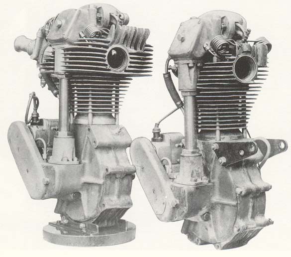
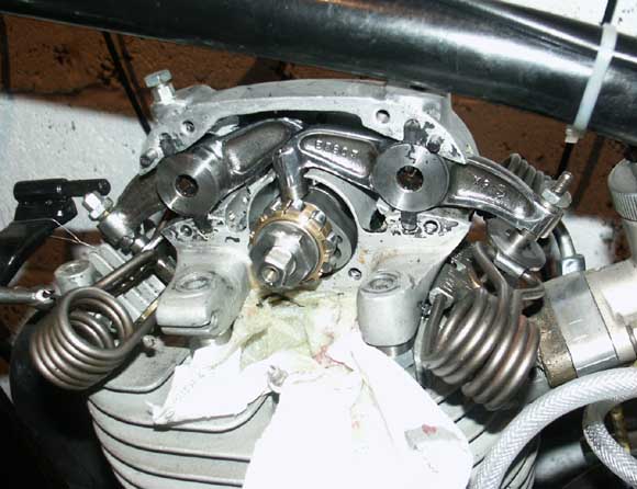
No, not mine I'm afraid, but one of my favourite
photo's of two pre-war 'Manx' spec racing engines.
Both are fitted with central oil feed cambox's
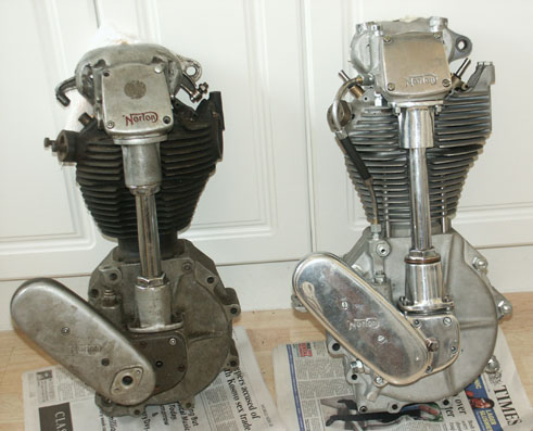
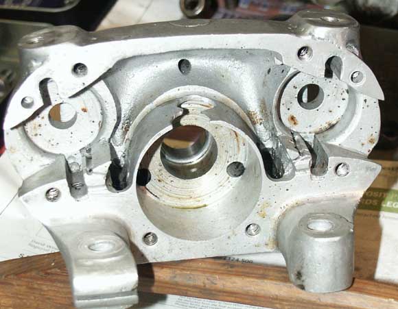
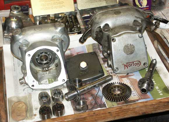
This photo shows my 1938 International on the right, as bought. The cambox at this stage is just an empty shell and has the standard road going oil feed
The cambox that came with the engine was a standard alloy version (not the racing magnesium version), and overall it was in very good condition. As such, it was fitted with the road going side oil feed as used by non-racing International’s, of which more later.
The main cambox casting particularly, did not show the normal horrors that can befall this component. It is not uncommon to find that the rear feet of the cambox have been broken off and re-welded. Even more common is to find that the aluminium ring that surrounds the cams (and is designed to capture oil being span out from the camshaft), has been broken away. Although this second fault is not too difficult to rectify (normally by machining a new ring and securing it in), it is still not a task to be taken lightly, so I was pleased it was not required. The rear cambox casting was also in good condition and as bought, the engine came with a new rear camshaft roller bearing for this backplate, which only required fitting. Interestingly, this bearing is actually bigger on the International than it is on the magnesium SOHC Manx version. Not quite sure why this is, but I do know that it is not cheap and becoming harder now to get hold off (postscript July 06 – I now stock these and other SOHC bearings if you require them, please go to my For Sale page to view my catalog).
The castings had even been cleaned up ready for assembly making my life even easier. So, other than ensuring the threads were ok and that the mating faces were made true (easy on the front face as this can be emery’ed on a surface plate, but more difficult on the rear face, as the rear legs get in the way), the only real job to do was to provide the means for a central oil feed.
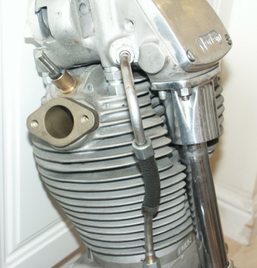
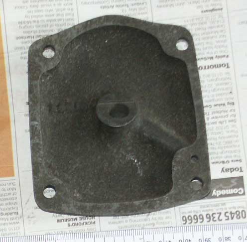
Another view of the cambox as purchased.
This photo clearly shows the rear oilway in use and the front boss
un-machined at this stage
As a dead giveaway on a SOHC Norton to differentiate a racing engine from it’s road going counterpart, is to look for a central oil feed to the camshaft, identifiable by a blind Hex nut in the centre of the front bevel inspection cover. The standard road going model does not have this central feed through the camshaft, instead relying on a side feed, that passes oil onto a grooved spacer ring in the centre of the cambox, where hopefully(!) it is passed down to the cams.
Both road and race going cambox’s look to use the same casting (although I have seen a few minor variations on the same theme), but the casting has provision for two separate oil bosses. The road going cambox takes its oil feed from the rear boss (closer to the central spacer, while the racing version uses the front boss (closer to the front bevel cover, which is fitted with an oilway from the side of the cambox’s mating face, to the centre of the instpection cover, from whence it feeds the camshaft.
As I had always intended to use this engine for sprinting and serious speed work, I knew this would be a ‘must have’ mod, and should result in less cam wear, as it gives direct oil feed to the camlobes. By the way, just in case you might think that high lift cams don’t have a difficult life, you should see some of the old ones I have in my possession, where the lifting face looks like it has been pressed up to a grindstone.
Luckily it is relatively easy to drill and tap the blank front boss to take an oil union, then very carefully drill the cambox with two oilway feeds, one from the boss side, the other from the front mating face. Hopefully, if you get it right!, they will both meet up in the middle, rather than drilling into the central cambox. This I was able to carry out successfully, even with both fingers crossed!
The camshaft is also different on a racing SOHC camshaft, as it requires
drilling down its centre to act as an oilway. The oilway from the bevel
inspection cover is then mated to the camshaft oilway via a phosphor
bronze spring loaded plunger, identical to the one fitted to the big
end feed. The plunger fits onto a similarly tapered plug fitted into
the near end of the camshaft.
Luckily, although my camshaft did not have a plug fitted it had already
been drilled deep enough to be used as an oilway for the cams (you need
very long reach 1/8” drills to get down far enough to reach the
furthermost cam). I machined up a suitable plug in aluminium and was
able to press this into the the camshaft, job done – or so I thought,
but more of this later.
Both ends of the camshaft are fitted with a large shouldered nut, one left hand thread and one right hand thread, as purchased, there were new ones of both supplied. The central grooved spacer (used to pass oil on the road going version, but purely a spacer on the racing version) was also in good condition, so it was only necessary to buy a few spacer shims and a cam woodruff key.
The new 'central feed' oilway on the cambox is visible here. You can also see the blocked off original feed
This photo gives a good view of both the upper
and lower slots for locating the rubber seals, including the new ears
that have been welded on at the top.
Note also the round camshaft tunnel in the centre that is often cracked
or broken off
An interesting point with the cambox casting supplied with this engine, was that someone had gone to the trouble of welding two additional ‘lumps’ to the top of the cambox, which had then been drilled and tapped to accept adjustable rubber seal tensioners. My initial reaction on seeing these when I purchased the engine was to think to myself ‘they need to come off!’ However on closer inspection, I noted they had been very well done, and actually seemed a very good idea.
For those of you not familiar with Norton cambox’s, they are very basic in their design particularly with regard to keeping the oil on the inside! The outer part of the valve rockers are exposed to the elements, while oil from the inner cambox is supposedly stopped from exiting the cambox by the use of rubber seals (proper ones also having a cloth like material running through their centre). This seal then presses against the central (bearing) part of the valve rockers, both top and bottom. Both the top and bottom seals fit tightly into a slot in the cambox casting, and if adjusted correctly should be pushed firmly against the rocker arms central area, which is basically round at this point, and whose profile remains constant as the rockers open and close the valves. Yes, I know that that probably all sounds very confusing, but hopefully the photographs make my explanation a bit clearer!
Anyway, what seems a slight flaw in Norton’s original design is that – to ensure that the rubber pad is always acting firmly against the valve rocker, they built in adjusters to the bottom pads, so they could be tightened as the pads started to wear. However, they didn’t bother to do this for the top adjusters, so as they wore there was no means to adequately take up the slop, at least not without stripping down the cambox and fitting packing pieces. With my particular cambox, someone had gone to a great deal of effort to alleviate this problem by building in the same style of threaded adjusters on top as were fitted at the bottom.
Admittedly my initial rationale for removing the lumps was for purely cosmetic, reasons, I thought they ruined the lines of the cambox and did not look original, however, after looking at their construction and realising they would not be visible once the petrol tank was in place I decided to keep them on for the moment. I did however, get my angle grinder out to them and removed some of the excess metal, so as to blend them in with the original casting more. The finished results don’t look to bad at all, perhaps Norton’s should have tried it themselves! My only concern was that I was not sure the rear cambox lump (inlet) would clear the top of my frame, once the adjuster was fitted.
Postscript July 06 : This concern turned out to be well founded, as the adjuster did foul the frame. After much trial fitting of engine in and out of frame, and some judicial metal removing from the cambox boss and top adjuster , I eventually managed a compromise. The front (exhaust) adjuster is fine, but the rear boss is now much shallower and the adjuster is almost flush with the cambox contour, without even room for a locknut. O.K. Norton’s – that’s probably why you didn’t bother trying this!
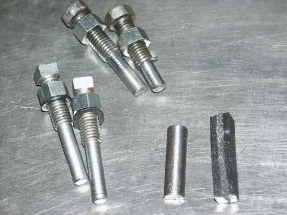
The rubber seal adjusters are shown here, complete
with a layered seal in the lower right corner. The half round metal
strip on the left of the rubber sits between the rubber and adjuster.
Note original square heads on lower adjusters
Side Washers, Cork
Seals and Rocker Bearings
I have already explained how the rubber seals are the primary means
of stopping oil escaping past the rockers, but it is probably worth
explaining the other rocker components in more detail.
The rockers themselves are substantial forgings, with pressed in rocker
pads at one end, that act upon the cam lobes. When purchased these pads
had not been fitted, but looked in good condition. I suspect they had
been taken out to have them stoned, which was nicely done so I refitted
them again.
Those that came with my engine were in very nice condition with no serious
blemishes and had also been very nicely polished. There was the smallest
indent on the exhaust rocker that co-incided with the exhaust valve
lifter, but this is to be expected on anything other than a racing engine
and even some of these are fitted with lifters (I also have a magnesium
Manx end cover which has provision for a lifter)
The other ends of the rockers are threaded to accept an unusual valve
tappet assembly, consisting of a slotted outer adjuster and an inner
tappet block and locknut. This inner tappet block has a male taper that
coincides with a corresponding female taper inside the outer adjuster.
The principle is, to adjust the tappet clearance first release the locknut,
which allows the inner taper to loosen off, then adjust the outer threaded
adjuster (it has a hex head at it topmost part), then retighten the
inner locknut which forces the taper to lock the outer adjuster again.
Unusual, but it seems to work well in practice.
With this particular engine the rockers had already been nicely polished
and the tappet adjusters all look to have been replaced. If memory serves
me right all I had to buy was a single locknut.
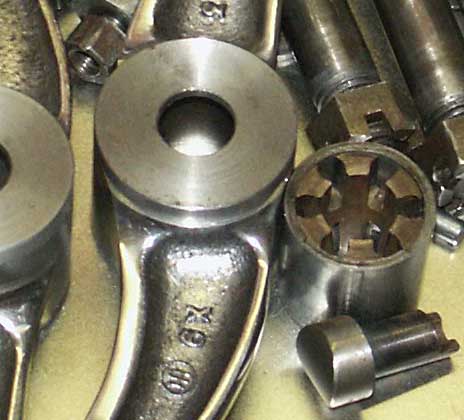
The rocker bearings themselves are also quite unusual, consisting of
a harderned steel outer cage pressed directly into the rocker arms.
Then a phosper bronze cage holding 12 small rollers, in two parallel
rows of 6 rollers each side by side. The rollers act directly on a hardened
steel rocker pin that feeds through the inner and outer cambox cover,
and is tightened in place using a special castellated nut, that can
be pinned if needed (haven’t bothered doing this myself).
The rear of the pin has a taper that fits into a corresponding taper
in the rear cambox cover, so as you tighten up the nut the pin should
always centre exactly and lock up fully, and ensure the pin does not
turn in the housing.
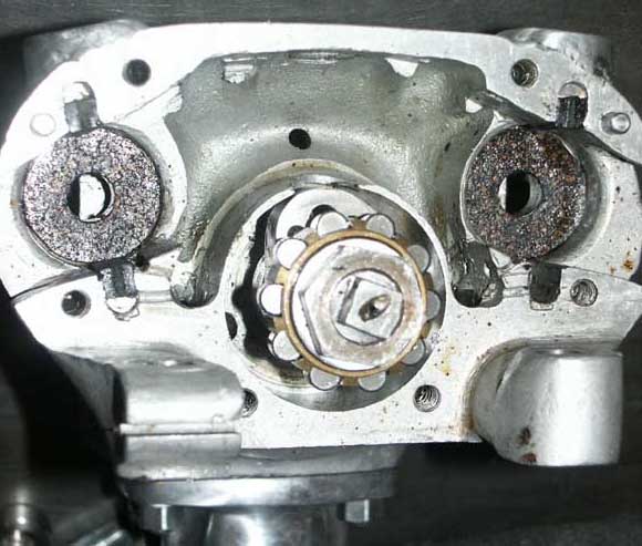
Another shot of the cambox, this time with rubber seals and cork washers fitted. The cams and bearings are also trial fitted at this stage
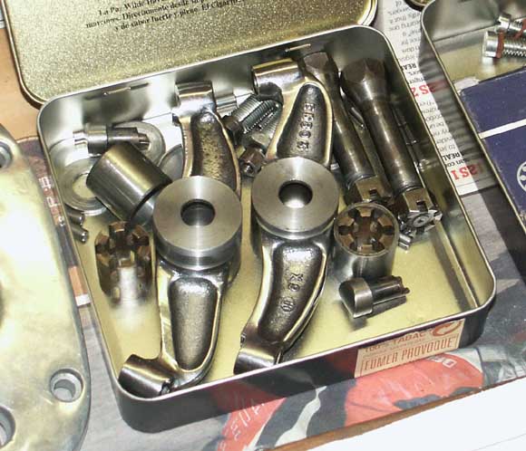
This tin of goodies includes the rocker arms and bearing pins, outer bearings and cages as well as the cam pads that are not pressed in at this stage
The side thrust of the bearing rollers is taken by hardened steel shim washers that press into the rockers from each side once the cage and rollers are fitted. Finally, over these on either side fits unhardened lipped washers, that as supplied with my engine looked to be brand new. Once the bearings are oiled and assembled these lipped washers are placed over each side of the rocker before assembling in the cambox.
The final component, which I assume is another aide to keeping the oil in, is the fitting of circular cork washers on either side of the lipped washers. These are fitted directly into each cambox casting and in my case were retained there by a light application of sealer.
This close-up shows the bronze cage and cupped washers in more detail
In its favour, I have seen quite a few of these cambox’s stripped down, and although the hardened side washers are often worn, very rarely do the rocker pins, rollers and cages look to have much wear, so I assume the design has stood the test of time.
I vaguely remember that JAP Speedway engines were of a similar design with their rockers, using loose rollers as well, but in J.A.Prestwichs’s case they did not bother with the bronze cage, those engines being slightly less exotic!
Incidentally, if you are buying one of these engines, the other problem area to look out for is on the rear cambox casting, around the tapered area of the exhaust rocker pin. I have seen these cracked, particularly on Manx versions and supposedly this is not uncommon. With magnesium this can be extremely difficult to repair.
All the components for the rockers supplied with my engine looked to be in very good condition. As I have mentioned in previously, one of the big selling points of this engine was that so many of the smaller parts had already been replaced, which can add up to a lot of money very quickly when you are faced with replacing them.
When I came to assemble them I first fitted the new cork washers into both cambox castings. I then assembled the caged rollers and pressed in the hardened side washers. However, when I fitted the lipped washers and then gave them a trial assembly in the cambox, I found that the rockers seized solid before finally tightening up. Eventually I was able to trace this fault back to the lipped washers, which turned out to be too thick. I have subsequently built another cambox with a similar problem and gather from Stu Rogers there are actually a couple of variations here. Anyway, after much trial and error and very careful skimming of the washers in my lathe I was able to assemble everything up ok.
The most important point to remember when the rockers and rubber seals/cork washers are fully assembled (without camshaft fitted I find easier), is that the rocker arms must be almost solid and very difficult to move by hand. If they are a sloppy or loose fit in the cambox they will almost certainly leak oil!
As I mentioned earlier in a previous article, the engine as originally purchased came with a very nice set of ‘International’ profile cams. However, as I was intending to use the engine for competition, running on Methanol, I wanted to replace these with full blown longstroke Manx cams. Luckily, Stu Rogers is able to supply these off the shelf, so getting hold of these was not the problem I was expecting it to be (and actually, considering the work that goes in to a set of these cams, complete with vernier holes, the price was not excessive either). One thing I have found after years of playing with the older British bikes is that half the battle is actually being able to find the parts, irrespective of cost. You only have to own an Italian bike like a Ducati for a short while to make you put price into perspective!
When I was racing Norton ES2 pushrod engines, in desperation I ended up making my own cam forming tool to grind cams to my own patterns, as they were not commercially available. Much as this was perversely rewarding (when they worked), quite honestly I would much rather just have bought them if they had actually been available!

This photo shows Manx Longstroke profile cams above, with slightly less lumpy International cambs below
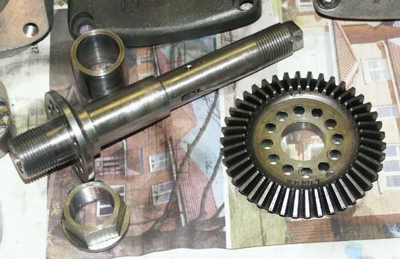
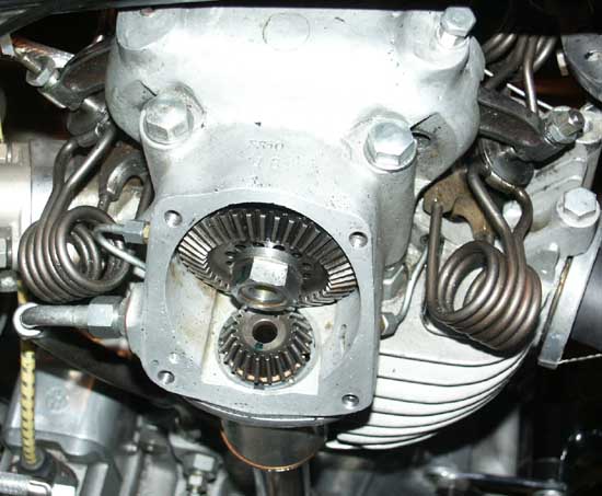
Shown here are the camshaft and large bevel gear, which highlights the method of vernier holes for moving the valve timing. The peg is held in by the shouldered nut
I will deal with assembly of the vertical bevel castings in another section, but save to say that both top bevels that came with the engine were original and in nice unblemished condition. Original bevels have a very distinctive oval trademark stamped on them and I have been told this is actually the same manufacturer as makes Coventry Dieheads – of which I also possess a few of in my workshop!
The large camshaft bevel has twice the number of teeth as the top vertical bevel and this (obviously!) gives the reduction in gearing of 2:1.
This top bevel is also very unusual as it has a series of holes around its inner circumference. As the camshaft has a similar set of corresponding holes at a slight number of degrees offsetb, it is possible to vary the valve timing just fractions by removing the pin that secures them together and changing holes. Very clever and effective. Mind you, it must be remembered this is only useful if the valve timing of both cams is out by the same amount, as both cams will move together using this adjuster. If only one cam is timed incorrectly then a similar vernier arrangement is also used to pin the cams to each other.
This shows the 1938 cambox next to another earlier cambox I have, of about 1933 vintage. No difference visibly, but internally different around the rockers
As I write this article it is difficult to know just how much detail I should go into to describe all the fun I had trial assembling the upper bevel gears and cambox, until I eventually got everything right! Save to say, you will breathe a sigh of relief to hear, that I will give you a much abated version!
If memory serves me right, I must have assembled and disassembled the cambox close to 15 times, until I had got everything right. But from doing this, what I did find out is that there is a logical order of assembly and fitting, that if followed in sequence should result in a cambox with gears that correctly mesh and is at least partially oiltight!
Cambox Bevel Cover
I didn’t really touch on it earlier, when I was talking about
the central oil feed, but of course once you have made this mod you
also require a bevel cover with a central feed to go with it.
The engine as purchased came with the standard aluminium ‘plain’
type cover, i.e. it has no oil feed, just the very pretty ‘Norton’
scroll on its lower part (placed here so it is visible beneath the fuel
tank).
Well as it happens, while on a visit to Stu Rogers for bits not long
after buying the engine, what should I spy on one of his shelves but
a genuine magnesium SOHC Manx type bevel cover. If truthful, it has
always been the more exotic ‘Elektron’ based magnesium Manx
parts that I have been most turned on by, so there was no way I could
let the opportunity of putting one of these on the bike slip me by,
so a deal was done.
Not much to say about the cover itself other than it was in very nice
condition and had a nice even finish to the chromating, giving it the
traditional Norton deep grey-black finish. Its centrally feed oilway
included the important central steel plunger boss, and all that was
needed was to purchase the correct hex head blind nut and raid a plunger
from my ES2 spares (they are the same as those used on both Inter and
ES2 big end feeds).
Incidentally, I could not resist holding both the magnesium and aluminium
covers together side by side. The difference in weight is actually quite
noticeable and you can understand why Norton’s employed this material
for their serious racing machines.
I will talk about the more exotic SOHC magnesium parts (and the upkeep
of magnesium alloys themselves) in a lot more detail in subsequent articles,
and as a taster, hope to be able to detail the build of a very rare
and pretty pre-war full magnesium 500cc Manx engine with square head
that I am currently re-building for one of my other bikes.
As a footnote, Stu Rogers cannot understand my fascination for all
things magnesium and likes to remind me of the term coined to describe
it by a well known senior manager at Norton’s – ‘Electrified
Dirt’!
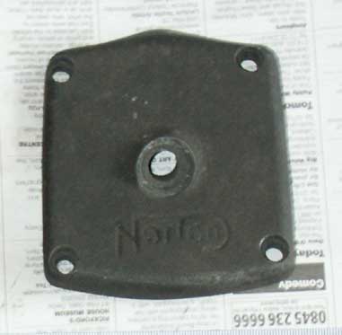
Here you can see the hole to take the quill for the central oil feed in the magnesium bevel cover
Same cover from the rear, showing how the oil is fed from the mating face
This I have found to be the best
order of assembly:
• Clean and prepare all parts. Have a variety of shims for the
camshaft and upper bevel casting to hand
• Fit front camshaft bearing and retainer plate, solder screws
heads
• Trial fit the valve rocker arms, cork side washers, steel dished
washers, rubber (or felt) seals, adjusters etc, without the camshaft
fitted. But do fit the backplate and tighten everything up as if you
are doing a final assembly. Fit the bearing pins so the rocker arms
are located correctly (although they do not need the castellated nuts
fitted at this stage). This allows you to get the best (tight) fit of
rockers without the camshaft getting in the way and stopping full movement
of the rocker arms
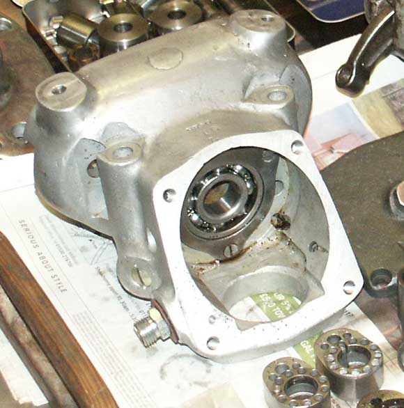
• Fit the rear camshaft bearing outer race in the rear cambox
cover, if fitting new bearings (– you are fitting new bearings
aren’t you? I do stock them you know . . . )
• Trial fit the camshaft with the large bevel gear attached and
all the relevant spacers, shims, cams and nuts fitted. Don’t worry
about woodruff keys and over tightening at this stage, we are doing
this purely to allow us to measure the bevel gear backlash. Ensure that
the rear inner bearing is not touching the back wall of the lipped outer
bearing at this stage (use grease in the race to verify this), as this
will affect the free play on the camshaft. Again, fit the backplate
with screws, so the camshaft is running true.
• Now trial fit the upper bevel casting with the bevel gear fully
assembled (see my Oldham Coupling section). Take a ‘best guess’
at the initial shimming for this. Adjust shimming to get best possible
backlash, as described above. You should now have the most critical
distance set correctly, that from the front bearing to the bevel gear.
• At this stage I check that the cams are centred correctly under
the valve rockers. On both this cambox and others I have played with
I have found this can be out slightly. I have either added shims or
removed a small amount of width from the central slotted spacer to ensure
these are central. Not sure if this is really necessary but it makes
me feel better
• Shim between cams and rear inner bearing to ensure that the
rear bearing rollers are fully acting on the outer race, without touching
the rear lip. To do this I smear thick grease over the outer bearing.
You should now have the camshaft fully shimmed
• Camshaft can now be final assembled. This includes fitting the
special front peg into the bevel gear and the cams being pinned to each
other, using the vernier holes. In my case, I chose initially to use
the recommended starting point of 1 and 6, as described in the Norton
Workshop Manual for SOHC Nortons. At this stage don’t bother over
tightening anything as it may be necessary to change the cams after
checking valve timing. Assemble valve rockers, fit backplate and rocker
pins (again, don’t bother with over tightening anything as cambox
might need to come down again.
• Check valve timing (see next section)
• Once the valve timing is correct, you can remove the cambox
and tighten up the camshaft nuts as tightly as you can, given that the
cambox is ‘loose’. That’s about it, for the moment,
you should now have a cambox ready for final assembly!
Final Assembly
I do not bother final fitting the rear cover until the engine is in
the frame and the final drive is connected up. This is because I have
found the only possible way to get the necessary torque setting on the
two camshaft nuts (55lb square inch), is to put the bike into gear with
the rear wheel locked and then use this to stop the camshaft from turning.
I spoke to Stu Rogers about this and he informed me he has found this
is the most reliable way to ensure those two nuts are torque’d
up tight enough.
Even Stu admits that he has never felt comfortable about exerting so
much pressure through the bevel drive train (obviously it is the bevel
gears that stops the camshaft rotating), but there is little alternative
if you want to ensure the nuts are really tight. Ahhh, you are probably
saying, but isn’t there a square on the end of the camshaft for
holding it in a vice when tightening? Well yes there is, but this is
not ideal for the torque setting’s we are talking of, and in many
cases when stripping cambox’s you will find this square badly
mauled.
To ease my conscience when tightening these nuts as described above,
I actually turn the engine over slightly a couple of times, in the process
of tightening. My rationale behind this is that it then ensures that
the full strain has not gone on just the same single bevel teeth.
Jumping ahead slightly, this photo shows the complete engine assembled in the frame, where the camshaft nut can tightened to the correct torque setting
Postscript July 06: I am
jumping ahead slightly here, as I found this out through hard experience
the first time I ran this engine for any length of time. The two nuts
loosened within minutes and wrecked the camshaft. I thought I had it
locked them up solid, but clearly it was not enough.
I was very fortunate in that when the nuts loosen, the cams and camshaft
are no longer held together as a solid unit, with the result that the
woodruff key shears and often wrecks not only the camshaft but the cams
as well. In my case, although the key had sheared and allowed the cams
to rotate, wrecking the soft camshaft, luckily the broken key had not
cracked the cam slot. It did however take me some considerable time
to remove the keyed cam from the camshaft, as the remains of the key
had fouled up the slot inside the cam, meaning it would not slide off
the shaft. After an hour with a torch and magnifying glass I was forced
to revert to my other keyhole surgery tools to remove the cam –
a large mallet and drift!
Next section : confirming the valve timing and setting the compression ratio
Another photo of the engine/cambox in the frame, this time showing the front bevel gears assembly. Green mark is to aid me when checking timing

Return To Top of Page