| |
|
|
|
|
|
|
|
|
|
|
|
|
|
|
|
|
|
|
|
|
|
|
|
|
|
|
|
|
|
|
|
|
|
|
|
|
|
|
|
| |
|
|
|
Building
the Engine - Part 1: |
|
|
|
|
|
|
|
|
|
|
|
|
|
|
|
|
|
Last
Updated : 07/05/10 |
|
|
|
|
|
|
|
|
|
|
|
|
|
|
|
|
|
|
|
|
|
|
|
|
|
|
|
|
|
|
|
|
|
|
|
|
|
|
|
|
Whats the Current Norton
Project?
Well, I havent really had much chance to work on my own bikes
much in the last few months, work, mail order and visiting friends
with illness have taking precedence. That said, since Xmas 2009
I have been very slowly building a 1937 International engine
which I am going to be using as a test bed ('Works Hack' I kid
myself) for testing new parts, in a rigid Inter roadgoing bike.
Anyway, I had a few days holiday this week, so have managed
to do a bit of work on it and having already done the prep work
on the main castings, I have now started the rebuild. I had
already checked and re-balanced the crank, cleaned up and blasted
the crankcase castings, so this week I have taken out the oil
pump and given it the once over, and have just finished fitting
the new main bearings.
For the engine rebuild, I thought it would be nice to treat
myself and spend a morning going through my own stock, to sort
out everything I needed - something I very rarely do, but I
had to remind myself - this was the main reason I originally
setup the spares manufacture - so I would have parts for my
own bikes! Anyway, I spent a couple of hours going through all
my stock and taking one (or two!) of everything - a bit like
Xmas! So the engine will be pretty much fully fresh on the inside
and have my full collection of parts in it: |
|
|
|
|
|
|
|
|
|
|
|
|
|
|
|
|
|
|
|
|
|
|
|
|
|
|
|
|
|
|
|
|
|
|
|
|
|
|
|
|
|
|
|
|
|
|
Preperation Work |
|
|
|
|
|
|
|
|
|
|
|
|
|
|
|
|
|
|
|
|
|
|
|
|
|
|
|
|
|
|
|
|
|
|
|
|
|
|
|
|
|
|
|
|
|
|
|
|
|
|
|
|
|
|
|
|
|
|
|
|
|
|
|
|
|
|
|
|
|
|
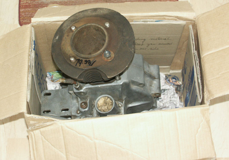
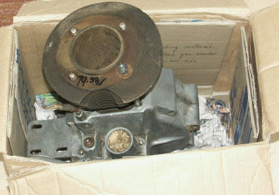 Inter in a Box!
1937 International engine as it arrived from Aussie
|
|
|
The basis for the engine
was a very straight and original 1937 International engine that
had come from my good friend Arthur Moore in Australia. As always,
Arthur had done a wonderful job of packing all the parts up safely
and had even included a little bit of Australian written culture
for me to read when I opened up the package - thanks for that
Arthur!
As with all Arthurs parts, the engine was lovely and unmolested
and exactly as he had described it - very much like it used to
be if finding an original engine at an autojumble 30 years ago.
Unfortunately nowdays, if an engine ever does come up for sale,
it is far more probable it will have been put together in the
last 6 months with a collection of non-matching dross.
I don't mean to get all weepy eyed and nostalgic, but when buying
parts from Arthur it reminds me what it used to be like when parts
were more plentiful here in England, and you could find engines
where there was a possibility you were the first person to have
looked inside it in the last 40 years, Ahh - them were the days
. . . |
|
|
|
|
|
|
|
|
|
|
|
|
|
|
|
|
|
|
|
|
|
|
|
|
|
|
|
|
|
|
|
|
|
|
|
|
|
|
|
|
|
|
|
|
|
|
|
|
|
|
|
|
|
|
|
|
|
|
|
|
|
|
|
|
|
Having unpacked the engine - which
was basically a complete bottom end and barrel + a spare barrel
that needed relinering, I carefully stripped it down and inspected
it. I found everything pretty much as I hoped to find it. the
crankcases were in excellent overall condition and I was very
pleased to find that the inner timing case, which is of the
'breathered' variety fitted in the late 1930's, shared the same
number as the crankcases - just confirming what I said earlier,
that this was an unmolested engine, with matching original parts.
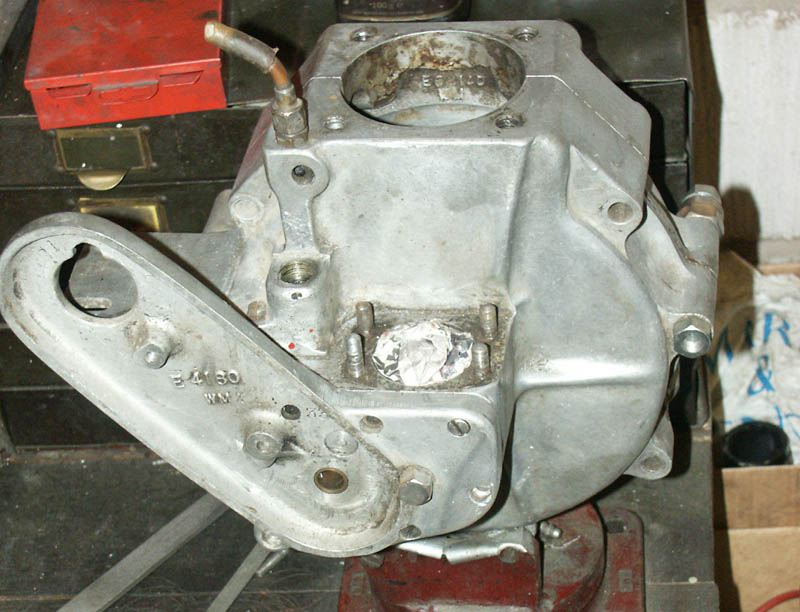
Note: In reference to the inner timing case breathing - there
were two variations. Standard 1930's engines have a hole in
them, above the oil pump drive bearing, that allows the timing
case to 'breathe'. This hole corresponds to a milled away area
of the timing case chamber on the timing side crankcase. Later
International engines, and magnesium timing covers did not have
these holes, as the crankcase timing chamber had a breather
union exiting out of the top |
|
 Crankcases, with
everything stripped, just before blasting.
Crankcases, with
everything stripped, just before blasting.
Notice breather hole in timing case, above lower
screw hole
|
|
|
|
|
|
|
|
|
|
|
|
|
|
|
|
|
|
|
|
|
|
|
|
|
|
|
|
|
|
|
|
|
|
|
|
|
|
|
|
|
|
|
|
|
|
|
|
|
|
|
|
|
|
|
|
|
|
|
|
|
|
|
|
|
|
|
|
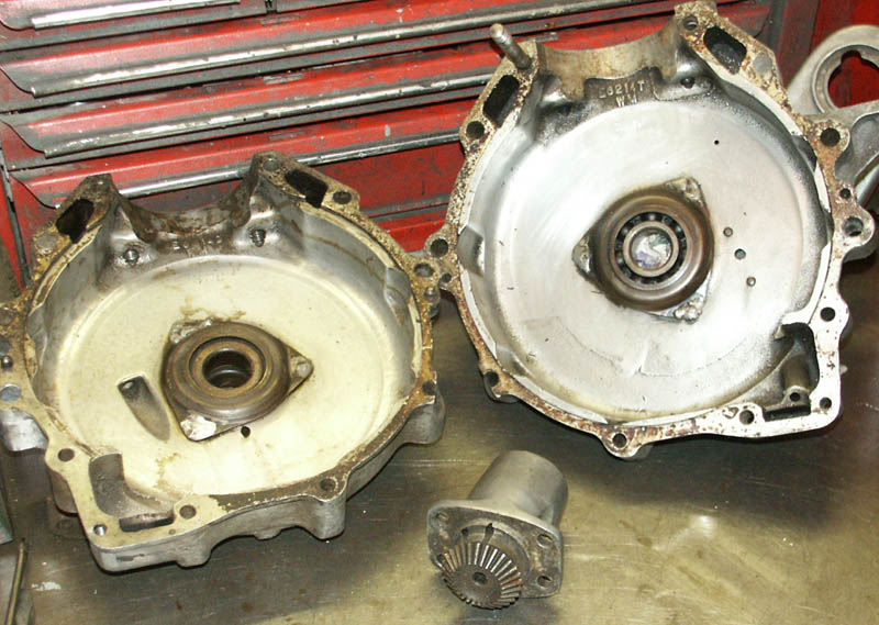
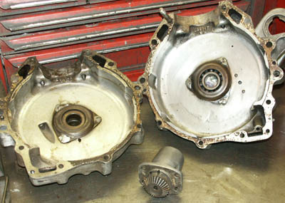 Inside of crankcases,
showing the original bearing retainer plates,
which I later removed to check the bearings. Bottom
bevel housing and gear also visible
Inside of crankcases,
showing the original bearing retainer plates,
which I later removed to check the bearings. Bottom
bevel housing and gear also visible
|
|
|
|
|
|
|
|
|
|
|
|
|
|
|
|
|
|
|
|
|
|
|
|
|
|
|
|
|
|
|
|
The drive side crankcase
had a small piece broken off it at the rear, on one of the engine
bolt surrounds - a very common problem and not serious at all.
I could have got away with leaving this, but I do not like anything
like this on an engine I am rebuilding (it would play on me
every time I looked at it!), so that and a small cosmetic 'knock'
on the timing case were set out for alloy welding. I did initially
attempt to carry out this welding myself - using my newish DHC
2000 oxy-acetylene torch, which supposedly makes alloy welding
a doddle. Although I had had some success with this new torch
(which has much greater heat control than the standard oxy-acetylene
torch I have been using for 20 years), I was not successful
with the crankcase and eventually had to concede defeat and
send the crankcase off to my normal welder in Leicester - Arthur
Sosbe.
Once the crankcase was back and cleaned up, I gave them and
the timing case a light blasting - having first carefully masked
up every orifice. Even so, the light blasting grit gets everywhere,
and when removing all the blocking material I had to very carefully
wash every oilway and cavity to ensure every spot of grit had
been removed.
My original intention was to get this engine\bike up and running
as quickly as possible. Although I want it to be mechanically
good - I do not want it to be too pristine because its main
purpose is to be a 'Works Hack' that can be used to quickly
test out any new parts on the road. I have mentioned this to
my best mate Andy Phillips and suggested he might like to be
a 'test rider' - where I give him the bike for a few days and
ask him to go and put a few hundred miles on it!
Anyway, as part of this - 'get it together quick' philosophy,
I was hoping I might get away with keeping the original Bigend
and Mains bearings in for the moment. On inspection, the Bigend
felt good and the crank very true, so that is worth keeping
for the moment.
However, although the mains initially felt fine, having gently
heated the crankcases up, so I could unsolder the bearing cover
plates to inspect the bearings - the timing case bearing virtually
dropped out, showing signs it had just started spinning in the
crankcase - not brilliant, but not uncommon at all. I carefully
inspected the crankcase bearing surround - to see how serious
the spinning of the bearing had become. There was just a slight
matt greyness, but no bad scoring, indicating that the bearing
had only just started to spin when hot - and therefore did not
yet warrant the serious remedial surgery of machining the crankcase
bearing area to take a sleeve - which is not something you want
to do unless you really need to. When there are signs that the
bearing is starting to slip though - it really needs to be replaced,
to ensure the best chance of full interference tolerence is
maintained, with new bearing.
Moving on to the drive side bearings, on heating up the crankcases
to remove the bearing retaining plate I found the bearings on
that side also came out quite easily, but on close inspection
of the roller bearing I found two things:
1. the bearings was not a lipped roller - not strictly necessary
if the spacer is correct - but it always should be!
2. the outer cage had corrosion on the bottom, where all the
weight had been sat over the years. This effectively made the
decision for me, yes the bearings will definitely all need to
be changed. (see further down)
Anyway, that made life much simpler, because it meant that I
did not have to worry about washing bearings out etc. I had
already committed to lightly blasting the cases externally,
and had carefully taped every orifice up with double layers
of Gaffa tape, but once I had made this decision to change bearings,
it removed any doubt about if this taping up had been unsuccessful
and eradicated the need to carefully rinse and degrease them
afterwards. |
|
|
|
|
|
|
|
|
|
|
|
|
|
|
|
|
|
|
|
|
|
|
|
|
 Very nice, straight
Inter crank, after a few hours cleaning it up.
It showed as running true as well
Very nice, straight
Inter crank, after a few hours cleaning it up.
It showed as running true as well
|
|
|
|
|
|
|
|
|
|
|
|
|
|
|
|
|
|
|
|
|
|
|
|
|
|
|
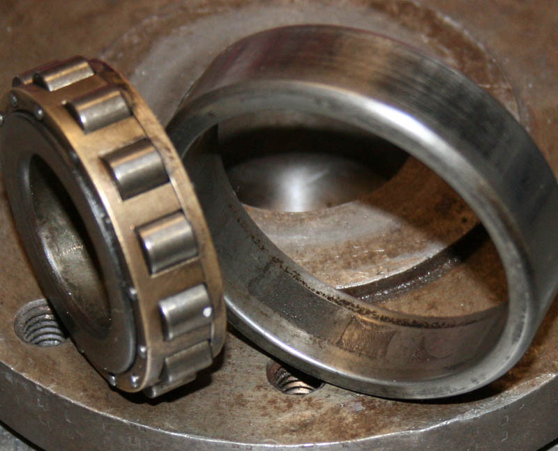
 The original
driveside roller bearing showed a definite
track mark, and the case hardening destroyed
in one spot - these would make a hell of a
noise if not replaced and would soon fail
completely. Note that this bearing is not
the lipped variety either - which it should
be
The original
driveside roller bearing showed a definite
track mark, and the case hardening destroyed
in one spot - these would make a hell of a
noise if not replaced and would soon fail
completely. Note that this bearing is not
the lipped variety either - which it should
be
|
|
|
|
|
|
|
|
|
|
|
|
|
|
|
|
|
|
|
|
|
|
|
|
|
|
|
|
|
|
|
|
|
|
|
|
|
|
|
|
|
|
|
|
|
|
|
|
|
|
|
|
|
|
|
|
|
|
|
|
|
|
|
|
|
|
|
|
|
|
|
|
|
|
|
|
|
|
Cylinder Head and Barrel |
|
|
|
|
|
|
|
|
|
|
|
|
|
|
|
|
|
|
|
|
|
|
|
|
|
|
|
|
|
|
|
|
|
|
|
|
|
|
|
|
|
|
|
|
|
|
|
|
|
|
|
|
|
|
|
|
|
|
|
|
|
|
|
|
|
|
|
|
|
|
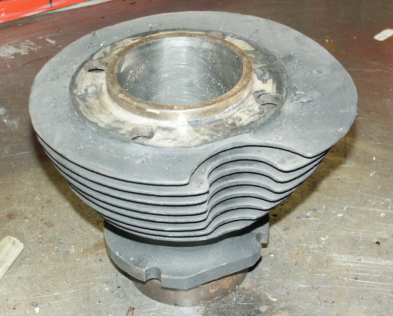
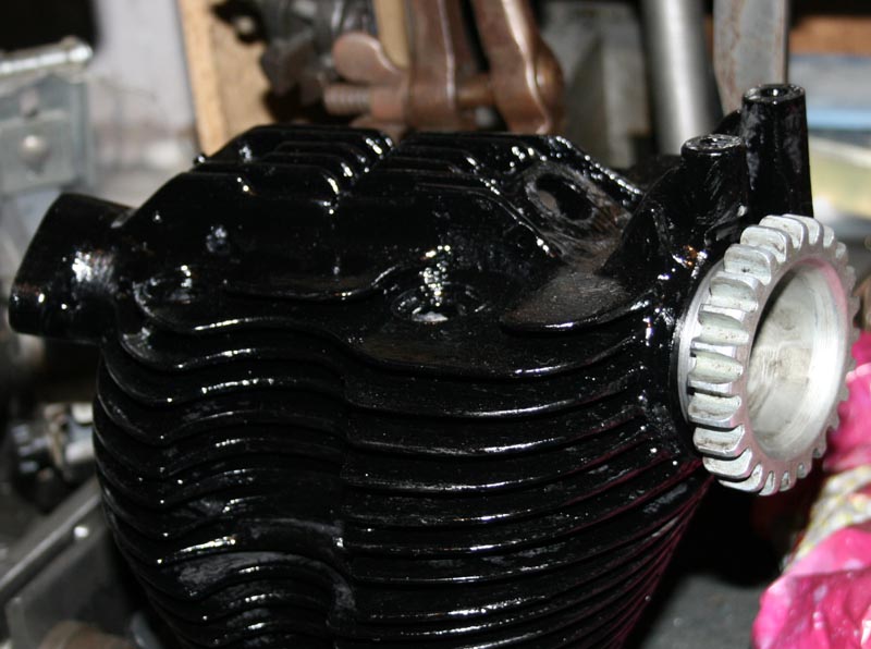
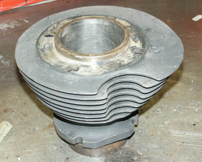 Nice condition
standard International cast iron barrel.
This is after honing and has just been blasted
and high temp painted
Nice condition
standard International cast iron barrel.
This is after honing and has just been blasted
and high temp painted
|
|
|
|
|
|
|
|
|
|
|
|
|
|
|
|
|
|
|
|
|
|
|
|
|
The barrel was nice and easy. As part
of the deal, Arthur had found two nice straight standard Inter
cast iron barrels. Both had all fins on them (an amazing rarity
in itself!), one was a good standardish size, just needing a rebore,
the other had been bored out until it had gone through the side
wall - which meant it would need re-linering, but this second
one was just a sweetener for the deal and would provide a good
basis for a future restoration.
For this build the first barrel was perfect, so all I needed to
do was give it a blast and then send it to my local car factor
motor engineers for a rebore, where it was ready for collection
within two days - job done!
|
|
|
|
|
|
|
|
|
|
|
|
|
|
|
|
|
|
|
|
|
|
|
|
|
|
|
|
|
|
|
|
|
|
|
|
|
|
|
|
|
|
|
|
|
|
|
|
|
|
|
|
|
|
|
|
|
|
|
|
|
|
|
|
|
|
|
|
|
|
|
|
|
|
|
|
|
|
|
|
|
|
|
|
|
|
|
|
|
|
|
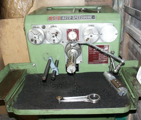
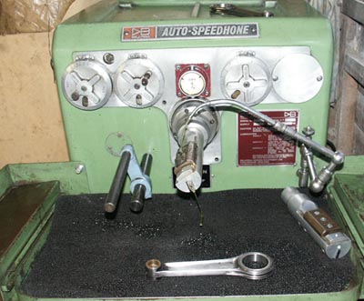 Delapena
Honing machine now installed in my workshop
- which means I can hone bigend eyes after
pressing them into conrod
Delapena
Honing machine now installed in my workshop
- which means I can hone bigend eyes after
pressing them into conrod
|
|
|
|
|
|
|
|
Incidentally, this visit
to my local auto engineers turned out to be very fortuitous for
another reason. They are a sikh family who have been refurbishing
car and lorry engines since the late 1960's. I can remember visiting
them in the late 1970's when I first started restoring bikes.
At one time they employed about 25 people and refurbished hundreds
of engines per month for fleets etc. Well now the original father
is close to retiring and his lads have other interests as well
as the automotive side, so the auto engineering business is much
smaller. I mentioned to him that I had been looking for a Delapena
honing machine for some time, for honing Bigends. With a wry smile
he told me to come round the counter and follow him to the workshops.
In a far corner, next to a huge and very expensive vertical borer\honer,
was a Delapena Auto Speedhone looking clean, but like it had not
been used for some time! It transpired it had gone out of use
about 10 years ago when they got the new machine, but that it
had had a very expensive service and bearings replaced just before
it was decommisioned (he reckons the service had cost well over
a £1000). He knew how good the machine was, so he was not
going to let it go cheap - but the clincher for me was looking
through the tooling that came with it and finding the correct
honing bar for Norton bigends in very good condition, plus a brand
new 'sizing ring' for same. These two alone to buy seperately
I had already found out would cost me approx £350 + VAT.
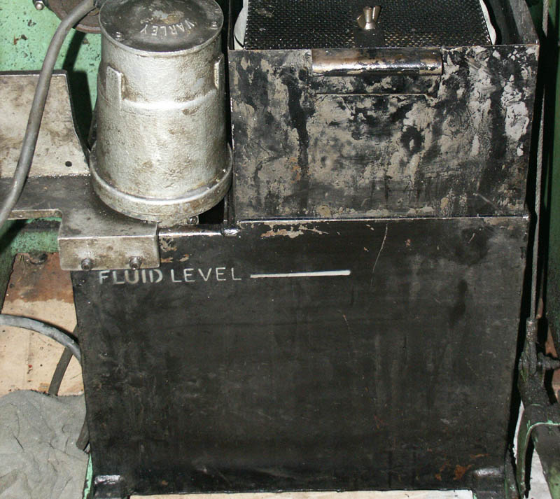
Needless to say, it was not long before a deal was done and the
honing machine was stripped down to a point where Andy and I stood
a chance of trollying it into the back of my van. Another little
bonus on stripping it was finding that it had a tank full of Delapena
honing fluid that I was told was brand new when they put the machine
out of service - approx 50 litres, or £120 quids worth.
Wahhay.
|
|
|
|
|
|
|
|
|
|
|
|
|
|
|
|
|
|
|
|
|
|
|
|
|
|
|
|
|
|
|
|
|
|
|
|
|
|
|
|
|
|
|
|
|
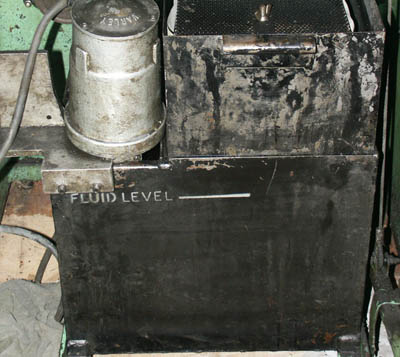 Tank
and filter system under Delapena is
quite elaborate and holds approx 50
litres of honing fluid
Tank
and filter system under Delapena is
quite elaborate and holds approx 50
litres of honing fluid
|
|
|
|
|
|
|
|
|
|
|
|
|
|
|
|
|
|
|
|
|
|
|
|
|
|
|
|
|
|
|
|
|
|
|
|
|
|
|
|
|
|
|
|
|
|
|
|
|
|
|
|
|
|
|
|
|
|
|
|
|
|
|
|
|
|
|
|
|
|
|
|
|
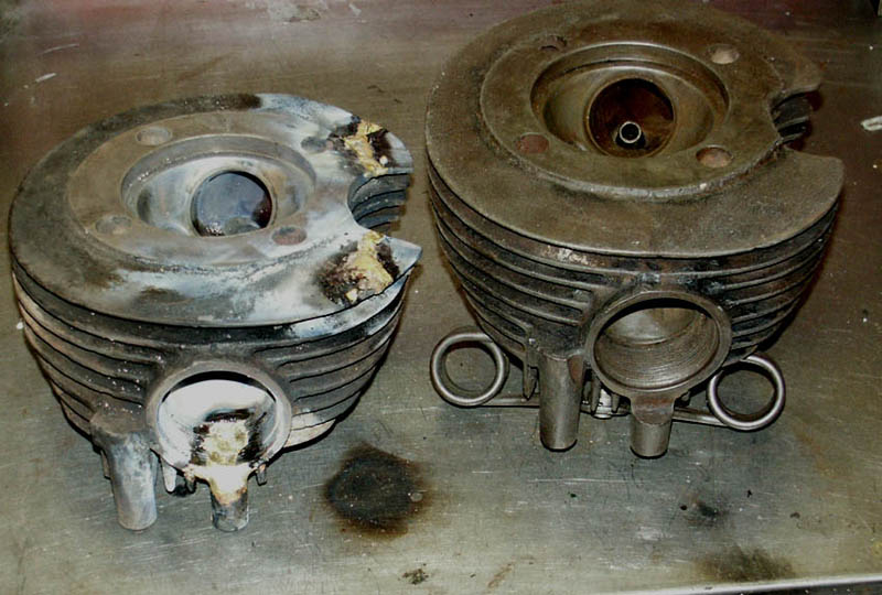
Cylinder Head Removation
As I had already mentioned, the bottom half had come from Australia
complete, but that meant the head and cambox needed to come from
elsewhere. Well luckily I already had a couple of standard iron
heads 'on the shelf', but the better one of the pair was really
part of a spare Inter engine which I wanted to keep together,
as it was all nice and orginal, with all the main castings in
good condition. This I had always considered my 'spare' engine
for the Racing Inter.
My other 500 spare head was in nowhere near as good a condition,
and I had always considered it as a 'last ditch' spare when I
had nothing else left. It had 3 key faults -
1. It had two broken fins surrounding the bevel tube cutaway (not
in itself serious)
2. It had the front head steady mount over the exhaust port broken
away (serious)
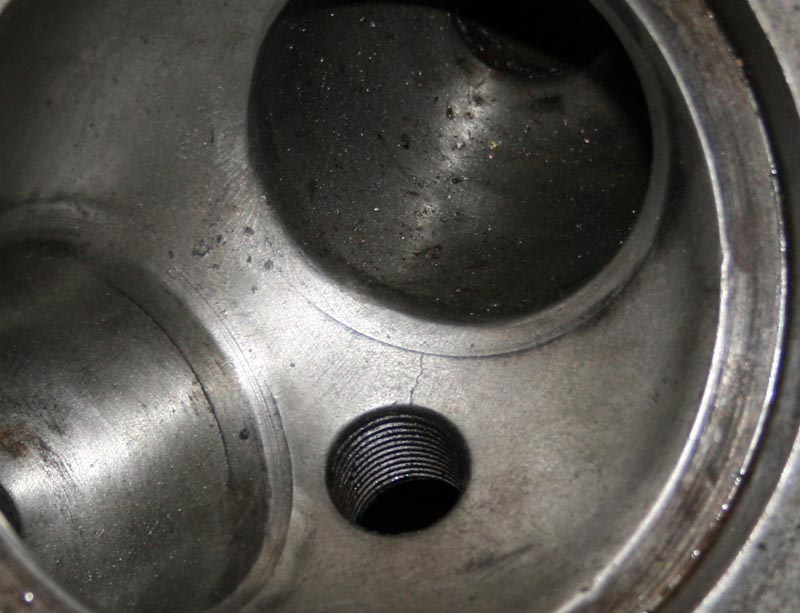
3. A common problem with iron heads - a crack from the spark plug
to exhaust valve seat (serious)
|
|
|
|
|
|
|
|
|
|
|
|
|
|
|
|
|
|
|
|
|
|
|
|
|
|
|
|
|
|
|
|
|
|
|
|
|
|
|
|
|
|
|
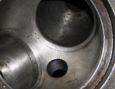 If
you look carefully you can just make
out a hairline crack running from
the exhaust port to the valve seat
If
you look carefully you can just make
out a hairline crack running from
the exhaust port to the valve seat
|
|
After some thought, I
figured that a little bit of extra work now, might result in turning
a sows ear into a silk purse, and mean I dont have to use up the
decent head - so I decided it was worth giving this head a go.
To address the simple problem first, I cut up a couple of steel
plates to roughly the same shape as the broken fins. I then put
these to one side, until I was ready to start brazing.
Secondly I looked at the crack between the spark plug and the
exhaust valve seat. I gave a lot of thought as to how to address
this. The important consideration was that a new exhaust valve
seat had been fitted at some time in the past, and therefore the
crack in the cylinder head only extended as far as the new seat.
This was important, because as far as I can tell, the most serious
issue around such a crack would be that a crack on the valve seat
would likely cause a hot spot and maybe burn out the valve.
As it was, after serious thought I have decided not to do anything
about this fault at the moment, I will suck it and see. If I do
need to do something I will grind out a channel (probably about
a centimetre in depth) along the length of the crack (about 7mm)
and have it cast iron welded - but this would mean having to remove
the valve seat as well and then fit a new one afterwards, quite
a radical operation, and maybe unnecessary.
Incidentally, when questioning what causes cracks like this, I
am not entirely sure - as it is not uncommon, but I suspect that
it is because the valve seat was fitted with an interference fit
that was too extreme and it overstressed the iron. |
|
|
|
|
|
|
|
|
|
|
|
|
|
|
|
|
|
|
 This
photo shows head just after being
brazed. New fins have been added and
exhaust port\heady steady rebuilt
This
photo shows head just after being
brazed. New fins have been added and
exhaust port\heady steady rebuilt
|
|
|
|
|
|
|
|
|
|
|
|
|
|
|
|
|
|
|
|
|
|
|
|
|
|
|
|
|
|
|
|
|
|
|
|
|
|
|
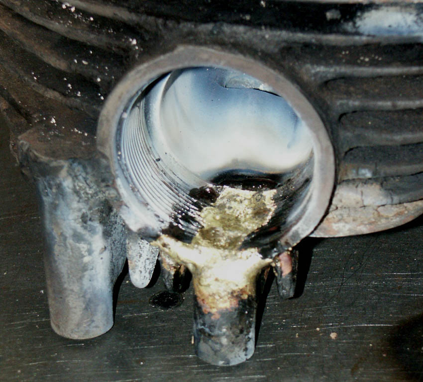
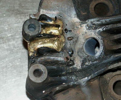
Exhaust Port Repair
The most difficult job was how to restore the exhaust port. It
looked like at some point in its life someone had dropped the
head and it had landed on one of the head steady posts, the one
that sits directly over the exhaust thread, and had completely
broken it away. It had been such a serious crack that even a section
of the exhaust port itself was missing, complete with thread.
However, the good news was that the crack ended just where the
threaded area finished, and it did not extend into the port itself,
therefore, providing a good exhaust washer was used to give a
full seal, then in reality the broken section could 'almost' be
considered cosmetic, as there was still a lot of good thread in
place to allow the exhaust nut to screw in. |
|
|
|
|
|
|
|
|
|
|
|
|
|
|
|
|
|
|
|
|
|
|
|
|
|
|
|
|
|
|
|
|
|
|
|
|
|
|
|
|
|
|
|
|
|
|
|
|
|
|
|
|
|
|
That did not change anything though,
I still wanted to effect a repair that would restore the exhaust
port to its original state, and once painted would look effectively
the same as the original.
To achieve this I had first to re-manufacture the missing piece
(or pieces as it turned) of the head steady and exhaust port.
Eventually this turned out to be 4 components - the upright threaded
'steady' component, manufactured from round bar on the lathe,
then drilled and tapped with the correct thread. 2 small vertical
fins that come off the steady, made from plate, and finally a
thicker piece of plate which when filed to shape could be wedged
into the broken exhaust port and act as a platform to mount all
the other 3 parts on, and then build around with brazing filler.
Once I had fabricated the parts, the next job was to braze them
to the head. Brazing is perfect for ths kind of job, due to its
excellent gap filling qualities, but there are a few tricks to
ensuring you get get good results and nice flowing fillets when
brazing cast iron. |
|
|
|
|
|
|
|
|
|
|
|
|
|
|
|
|
|
|
|
|
|
|
|
|
|
|
|
|
|
|
|
|
|
|
|
|
|
|
|
|
|
|
 As
can be seen, at this point the braze
has completely covered the plate
of steel that had been placed inbetween
the broken port, and has been directed
to fill the remaining gaps
As
can be seen, at this point the braze
has completely covered the plate
of steel that had been placed inbetween
the broken port, and has been directed
to fill the remaining gaps
|
|
|
|
|
|
|
|
|
|
|
|
|
|
|
|
|
|
|
|
|
|
|
|
|
|
|
|
|
|
|
|
|
|
|
|
Brazing Cast Iron
First off, it goes without saying that all parts to brazed must
be spotlessly clean and have any oxide or dirt removed. To achieve
this with cast iron I will normally use a rotary wire brush -
but blasting is better.
Probably the most important factor when you are dealing with cast
iron (either brazing or welding) is the use of pre and post heat.
This is absolutely vital to ensure that you have enough heat in
the head so that the braze will melt, instead of the head just
absorbing the heat given off the torch. It will also ensure that
the head does not crack, which is always a risk with cast iron
if it is heated up or allowed to cool too quickly - for this reason
the head needs to be post heated and allowed to cool down slowly
after the brazing is complete. The kitchen oven is perfect for
this task (I am sure your wife wont mind, mine is used to it .
. . ), you need to keep it in until the head is 'spit hot', i.e.
you can spit on the head and you see the spit immediately bounce
off.
Obviously, you need to use proper brazing flux for this job, I
normally mix a small amount with water, which I brush on to the
areas to be brazed, to protect them from oxidisation and aid flow,
but I also dip the brazing rod into the powder. If I remember
correctly (from my college welding days) it is also a good idea
not to use a strong oxidising flame with cast iron as this increases
the chances of cracking, instead a neutral or slightly acetylend
flame is best.
Finally, when you commence the braze, it is very important to
put the flame to the area to be brazed and let the brazing rod
flow to the heat. It can be very disconcerting when brazing cast
iron, because of the amount of heat the head absorbs, and a common
fault is to place the rod into the flame in vain effort to melt
the braze, where it just 'globulises' (not sure if that is a real
word, but I like it), but does not adhere to the base metal. If
you get it right, the braze should just flow onto the area to
be brazed and you can get it to follow the torch, nicely flowing
across the base metal as it goes, and building up a pool on the
surface (or fillet if desired) as you progress. It is important
to remember that brazing does not provide 'penetration' with the
base metal, unlike welding, therefore there must be a certain
amount of 'pool' over the two pieces of metal to be joined, to
ensure strength in the join afterwards. This is important to remember
when grinding down the braze of any fins you have had to repair.
By the way, it goes without saying that one of the most difficult
facets of cast iron (welding) is that it tends to 'collapse' when
it gets molten - if that starts to happen when you are brazing
it, then you are using too much heat! |
|
|
|
|
|
|
|
|
|
|
|
|
|
|
|
|
|
|
|
|
|
|
|
|
|
|
|
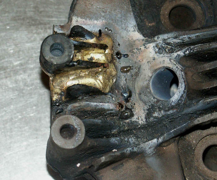
 Looking
down on the re-fabricated head
steady from above, you can see
the two small fins that were welded
to the threaded upright, before
the whole unit was brazed in place.
I then ensured braze flowed around
the full area, to fill any gaps
between the fins. Small beads
to the right of braze are the
remnants of the flux
Looking
down on the re-fabricated head
steady from above, you can see
the two small fins that were welded
to the threaded upright, before
the whole unit was brazed in place.
I then ensured braze flowed around
the full area, to fill any gaps
between the fins. Small beads
to the right of braze are the
remnants of the flux
|
|
|
|
|
|
|
|
|
|
|
|
|
|
|
|
|
|
|
|
|
|
|
|
|
|
|
|
|
|
|
|
|
|
|
|
|
|
|
|
|
|
|
|
|
|
|
|
|
|
|
|
|
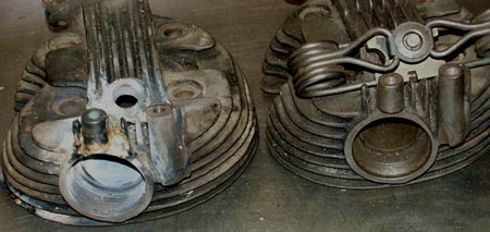 Completed
head with the newly fabricated
head steady on the left. On
the right is my other spare
Inter head, as comparison
Completed
head with the newly fabricated
head steady on the left. On
the right is my other spare
Inter head, as comparison
|
|
|
|
|
|
|
|
|
|
|
|
|
|
|
|
|
|
|
|
|
|
|
|
|
|
|
|
|
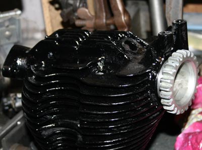 Finished
head after a first coat of
paint. I am pleased to say
it is pretty much indistinguishable
from the other head
Finished
head after a first coat of
paint. I am pleased to say
it is pretty much indistinguishable
from the other head
|
|
|
|
|
|
|
|
|
|
|
|
|
|
|
|
|
|
|
|
|
|
|
|
|
|
|
|
|
|
|
|
|
|
|
|
|
|
|
|
|
|
|
|
Anyway, so much for the theory . .
.
As it happens, in this case the job went reasonably well. Having
first got the head suitably spit hot, I was then able to braze
in the small wedge of steel into the exhaust port. Once I had
got this far I was able to rest the upright head steady post on
it (I had already welded the two small upright fins to the post)
, and then braze the entire post to the base. |
|
|
|
|
|
|
|
|
|
|
|
|
|
|
|
|
|
|
|
|
|
|
|
|
|
|
|
|
|
|
|
|
|
|
|
Once I had all the pieces in place,
I then very carefully built up the braze pools, first on top of
the exhaust port, then turning the head over and working from
the thread side, until I was happy that any indents had been filled
and the shape was basically flush with the original contours.
Normally when brazing I would not be too fussed about building
up the braze more than needed, then reshaping with grinder and
file afterwards. However, with this job I was aware of how difficult
and fiddly it would be too grind down the braze aftewards, so
I was more particular to ensure that I kept braze to a minimum
and only filled the area as economically as was needed. In this
case, luckily things went well and I was soon able to return the
head to the oven to let it cool slowly.
With the brazing of the head steady completed, and looking pretty
reasonable, the remaining jobs - i.e. fitting new valve guides,
cutting the seats and fitting valves will wait until a new batch
of valve guides I am having made are ready, which as I write this
in mid May, should not be more than a few weeks. |
|
|
|
|
|
|
|
|
|
|
|
|
|
|
|
|
|
|
|
|
|
|
|
|
|
|
|
|
|
|
|
|
|
|
|
|
|
|
|
|
|
|
|
Balancing Crank |
|
|
|
|
|
|
|
|
|
|
|
|
|
|
|
|
|
|
|
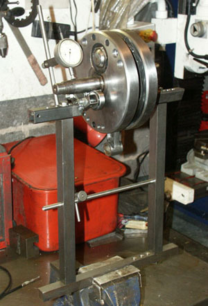 Crank balancing tool,
ideal for the job
Crank balancing tool,
ideal for the job
|
|
|
|
|
|
|
|
|
|
|
|
|
|
|
|
|
|
|
|
|
|
|
|
|
|
|
|
|
|
|
|
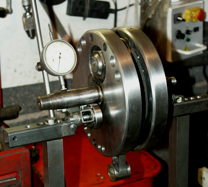
As I mentioned earlier in the article,
I had previously checked the crank for trueness, it running within
2 thou (thousandths of an inch) across its full length. The Bigend
bearing also felt pretty good, so I decided to leave well alone
for the moment – there is no point wasting a perfectly serviceable
original Bigend, we will see if it stays good, given the state
of the main bearing – although I expect it will last at
least a couple of thousand miles, (about 10 years use at my current
burn rate).
To measure run out on crankshafts, I had made my own crank balancing
frame some time before, and very useful it is too (after many
years of using some large steel pillars I have, with vee blocks
on top). This frame is fabricated from some very substantial solid
1” square bar I found in my dad’s workshop (thanks
dad – I heard you swearing as I ‘borrowed’ it),
and I then fitted a round bar assembly, with adjusters for holding
a dial gauge. Rather than vee blocks I then made a fabricated
assembly for holding 4 ball bearing assemblies, in vee formation,
that the crank could sit on. One of these sits slightly higher
than the other, as Norton mainshafts are of different diameter.
The whole top assembly is adjustable for width, as is the main
frame, for dealing with different cranks. It does not take up
much room, and is just bolted into the vice when needed. It is
well worth making one if you are intending to assemble cranks,
or change balance factors (necessary whenever you change piston’s
with differing weights).
|
|
|
|
|
|
|
|
|
|
|
|
|
|
|
|
|
|
|
|
|
|
|
|
|
|
|
|
|
|
|
|
|
|
|
|
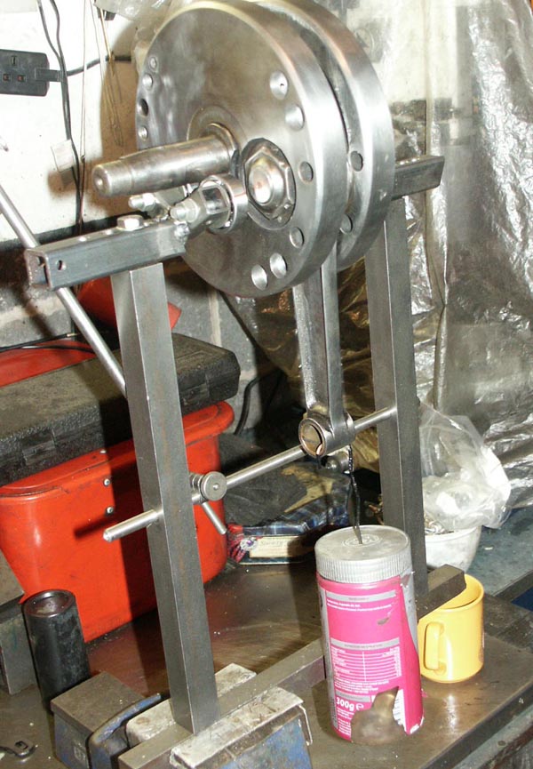
Calculating Balance Factor
Balance factor for SOHC Norton 500 engines should be approx 66%-68%,
erring towards the 68% (although I suppose this depends what revs
you intend to run the bike at). Some time ago I was fortunate
enough to buy a couple of lovely original Hepolite International
(petrol) pistons off that old Norton stalwart, Julian Harvey (Hi
Julian if you are reading). One of these pistons would be perfect
for this engine, so I measured its weight (with gudgeon pin and
circlips), weighed an International conrod, and estimated the
top third of its mass (this is considered the reciprocating element
of a conrod) and added up the sum of these elements. I then calculated
what 67% of that mass would be. I then subtracted the top third
weight of the conrod from this final amount (don’t forget
that when balancing the conrod weight is already attached to the
crankshaft!), and that gave me the final weight I needed to hang
from the crankshaft to give a ‘neutral’ balance when
balancing – i.e. the crankshaft should not stop in any one
spot.
I have a collection of small brass weights I use for this, and
a plastic screw top peanut container, with a wire hook which is
perfect for hanging on the end of the crankshaft. Initially I
hung this from the crankshaft and then placed weights in it until
the crankshaft was neutral. I then placed the container on an
accurate set of scales, and took a reading, which told me it was
50 grams out from the desired rate – hey presto. |
|
|
|
|
|
|
|
|
|
|
|
|
|
|
|
|
|
|
|
|
|
|
|
|
|
|
|
|
|
|
|
|
|
|
|
|
|
|
|
|
|
|
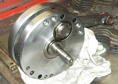
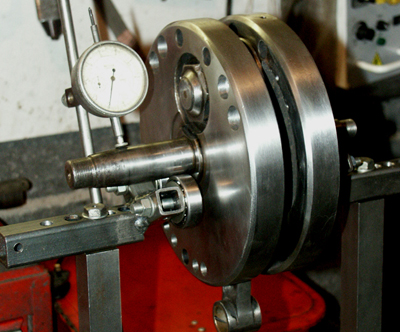 Stage 1: Having cleaned
up the crank, I measured it for trueness, on my crank balancing
setup - it was within 1.5 thou" along its full length
- which is good
Stage 1: Having cleaned
up the crank, I measured it for trueness, on my crank balancing
setup - it was within 1.5 thou" along its full length
- which is good
|
|
|
|
|
|
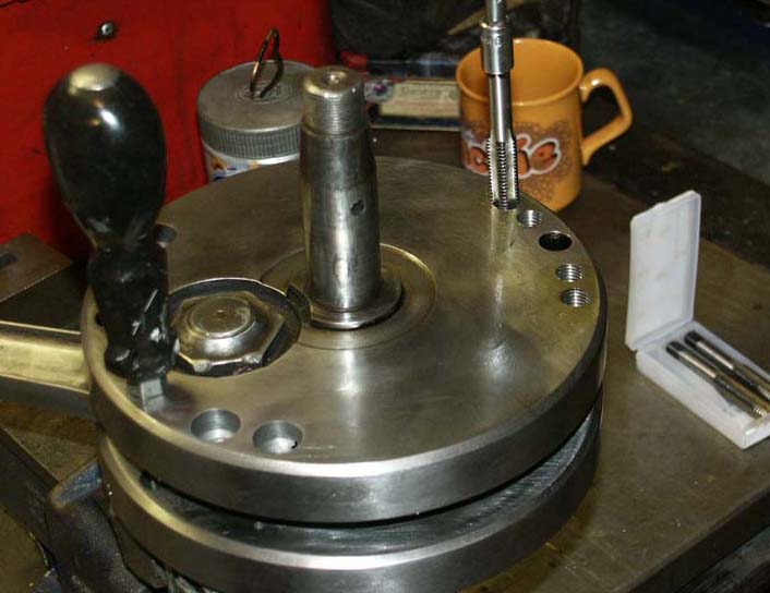
 Stage 2: To get balance
factor to 67% using Hepolite Inter piston, I needed to
add 50 gram to bobweight side. I tapped holes (12mm) to
take plugs on both flywheels
Stage 2: To get balance
factor to 67% using Hepolite Inter piston, I needed to
add 50 gram to bobweight side. I tapped holes (12mm) to
take plugs on both flywheels
|
|
|
|
|
|
|
|
|
|
|
|
|
|
|
|
|
|
|
|
|
|
|
|
|
|
|
|
|
|
|
|
|
|
|
|
|
|
|
|
|
|
|
|
|
|
|
|
|
|
|
|
|
|
|
|
|
|
|
|
|
|
|
|
|
|
|
|
|
In this case it was the bobweight
side (opposite Bigend) that was light, which did not surprise
me, because it looked like this side had had additional lightening
holes added at some time in the past. I ‘ummed and ‘aahed
for some time on the best way to get round this, but thought in
the end the most expedient method would be to drill and tap those
holes, so I could add Hex head (i.e. Allen spanner) grub screws
of varying lengths. Doing this has the advantage that if I change
pistons at some time in the future, adjusting balance factor should
simply be a case of changing grub screws.
I decided on a 12mm metric thread, as hex head grub screws in
this size are easy to get, and come in a variety of lengths. I
bought a 3 piece tap set (course thread) and then it was just
a case of carefully tapping each hole – first with the taper
tap to ensure the thread started easily, then finally the plug.
This is a big thread, so if you try it yourself make sure the
flywheels are held firmly in a vice (in the photograph you will
see a large screwdriver inserted on the opposite side to stop
the flywheel spinning) and use plenty of fluid.
I then measured out 4 plugs that approximately equalled the missing
weight and screwed them in, two on each flywheel, one on either
side of the mainshaft\Bigend centre line. |
|
|
|
|
|
|
|
|
|
|
|
|
|
|
|
|
|
|
|
|
|
|
|
|
|
|
|
|
|
|
|
|
|
|
|
|
|
|
|
|
|
|
|
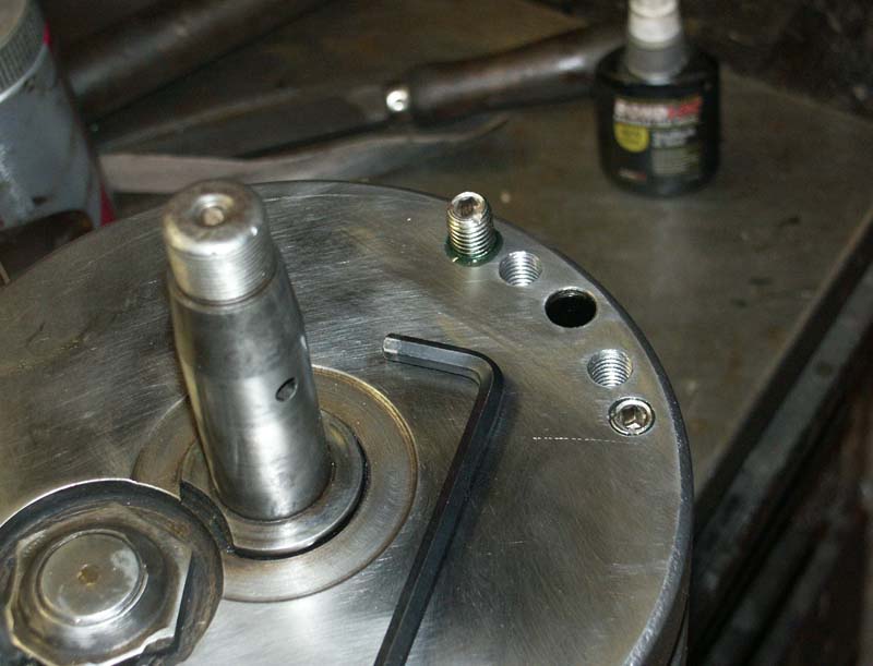
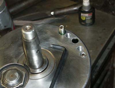 Stage 3: Having previously
worked out the number of inserts neeeded to get to the
required weight - I then screwed these hex plugs into
the flywheeels with Loctite
Stage 3: Having previously
worked out the number of inserts neeeded to get to the
required weight - I then screwed these hex plugs into
the flywheeels with Loctite
|
|
|
|
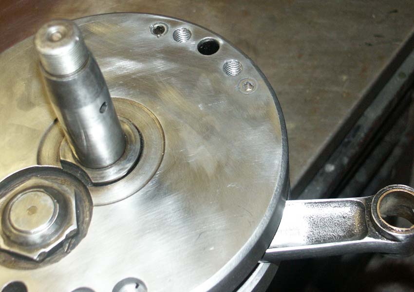
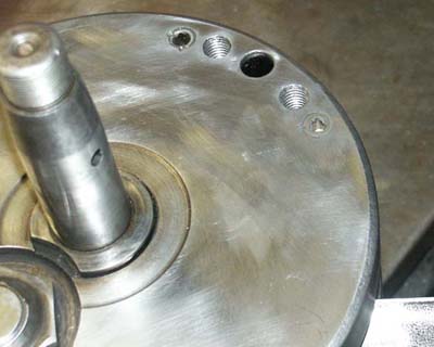 Stage 4: Final task
was to centre punch the inserts - I had previously put
a nick in the head of each one, for this purpose
Stage 4: Final task
was to centre punch the inserts - I had previously put
a nick in the head of each one, for this purpose
|
|
|
|
|
|
|
|
|
|
|
|
|
|
|
|
|
|
|
|
|
|
|
|
|
|
|
|
|
|
|
|
|
|
|
|
|
|
|
|
|
|
|
|
|
|
|
|
|
|
|
|
|
|
|
|
|
|
|
|
|
|
|
|
|
|
|
|
|
|
|
|
|
 Stage 5: As can be
seen, with the correct weights hanging from the conrod
(in plastic container), the Bigend eye sits almost
midway - which equates to 67% balance factor
Stage 5: As can be
seen, with the correct weights hanging from the conrod
(in plastic container), the Bigend eye sits almost
midway - which equates to 67% balance factor
|
|
|
|
|
|
|
|
|
|
|
|
|
|
|
|
|
|
|
|
|
|
|
|
|
|
|
|
|
|
|
|
|
Before finally screwing the grub screws
in, I just attached them temporarily, so I could check the balance
factor once again (don’t forget the tapping operation will
move a little bit of weight), this was now pretty much spot on
– good stuff!
I used Studlock fluid on the grub screws to stop them shifting,
but for added security I also ground a couple of nicks in the
head of each one, which I centre punched once they were tightened
into the flywheels for additional security. I was quite pleased
with this in the end, and hope this will provide a relatively
smooth engine in use – as always, we will see. |
|
|
|
|
|
|
|
|
|
|
|
|
|
|
|
|
|
|
|
|
|
|
|
|
|
|
|
|
|
|
|
|
|
|
|
|
|
|
|
|
|
|
|
|
|
|
|
|
|
|
|
|
|
|
|
|
|
|
|
|
|
|
|
|
|
|
|
|
|
|
|
|
|
|
|
|
|
|
|
|
|
|
|
|
|
|
|
|
|
|
|
|
|
|
|
|
|
|
|
|
|
|
|
|
|
|
|
|
|
|
|
|
|
|
|
|
|
|
|
|
|