|
|
|
|
|
|
|
|
|
|
|
|
|
|
|
|
|
|
|
|
|
|
|
|
|
|
|
|
|
|
|
|
|
|
| |
|
|
|
Building
the Engine - Part 2: |
|
|
|
|
|
|
|
|
|
Last
Updated : 25/05/10 (Published
07\10) |
|
|
|
|
|
|
|
|
|
|
|
|
|
|
|
|
|
|
|
|
|
|
|
|
|
|
|
|
|
|
|
|
|
|
|
|
Fitting
Oil Pump and New Main Bearings
In part 1 of this project I said that originally I was hoping
to re-use the original main bearings, as initially they had
felt to be in good condition and there was no point replacing
them if not required. However, in the process of removing the
original bearing retaining plates - which I needed to do in
order to get a good look at the bearings (and gave me the excuse
to replace these original plates with my own bearing plates),
I had found that actually there were tell tale track marks and
pitting in the roller bearing, indicating it was scrap.
Even before I had looked at the drive side roller, I had removed
the timing side bearing retaining plate, and a potentially more
serious problem had manifested itself, in that just heating
up the bearing plate with a blowtorch, so as to melt the solder
had put enough heat into the crankcase that it had caused the
timing side main bearing to drop out.
Normally a main bearing should only drop out once the crankcase
had been put in the oven for some time, so this was not a good
sign. |
|
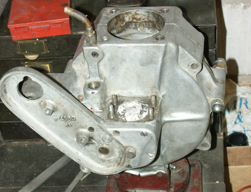
 Crankcases, with everything
stripped, just before blasting.
Crankcases, with everything
stripped, just before blasting.
Notice breather hole in timing case, above lower screw hole,
not fitted on all engines |
|
|
|
|
|
|
|
|
|
|
|
|
|
|
|
|
|
|
|
|
|
|
|
|
|
|
|
|
|
|
|
|
|
|
|
|
|
|
|
|
|
|
|
|
|
|
|
|
|
|
|
|
|
|
|
|
|
|
|
|
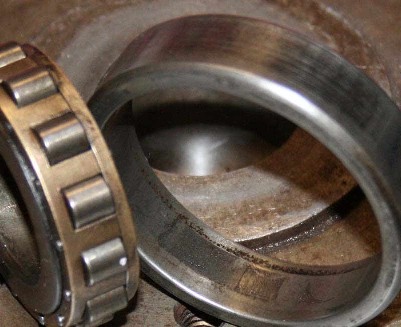
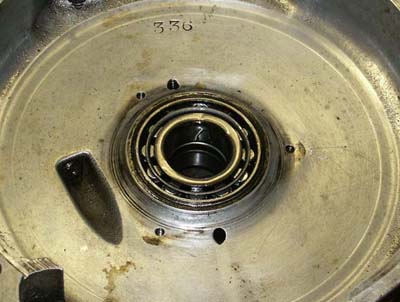
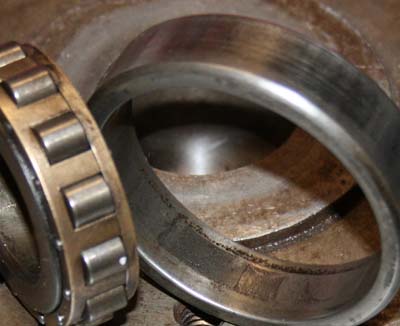 As I touched on in
Part 1, the original roller main bearing had seen
better days, and was just showing signs of having
started spinning - see slight marks on outer track
As I touched on in
Part 1, the original roller main bearing had seen
better days, and was just showing signs of having
started spinning - see slight marks on outer track
|
|
|
|
|
|
|
|
|
|
|
|
|
|
|
|
|
|
|
|
|
|
|
On
close inspection of the bearing wall of the crankcase, there were
slight signs of the bearing starting to spin, a faint greyness
of the metal, and corresponding marks on the outer track of the
bearing. If this was allowed to continue it would soon result
in the crankcase journals becoming worn and ruined, then would
need to be sleeved and jig bored - a complicated and costly job.
In the case of this engine it looks like I might just have caught
them in time, but it made the decision to change the bearings
very simple.
It will be something I need to be aware of when I run the new
engine, because although I think it had only just started to occur,
and I will use bearing fit when I fit the new bearings, I need
to ensure that this does not continue to happen - as it will soon
destroy the housings.
I am fitting the correct 'C3' type bearings, as were originally
fitted to these engines, which have a looser tolerence than the
standard size bearings and because of ths extra tolerence are
less inclined to spin. Anyway before I get to fitting the new
main bearings, what about the oil pump? |
|
|
|
|
|
|
|
|
|
|
|
|
|
|
|
|
|
|
|
|
|
|
|
|
|
|
|
|
|
|
|
|
|
|
|
|
|
|
|
|
|
|
|
|
|
|
|
|
|
|
|
|
|
|
|
|
|
|
Oil
Pump Refurbishment
It is always a difficult choice when refurbishing these engines,
trying to decide if the oil pump should be removed and checked,
as this is not always an easy task?, however, I would advise that
if there is any doubt as to the condition of the oil pump, or
if you are not familiar with the engines history, then this should
be removed and checked. It is a good idea first to check if the
pump drive will revolve freely, as that will give some clue, but
if there is any kind of roughness or locking up, do not force
the gears, this might make matters worse - just wait until the
pump is removed and then strip it. |
|
|
|
|
|
|
|
|
|
|
|
|
|
|
|
|
|
|
|
|
|
|
|
|
|
|
|
|
|
|
|
|
|
|
|
|
|
|
|
|
|
|
|
|
|
|
|
|
|
|
|
|
|
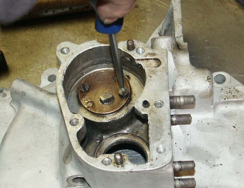
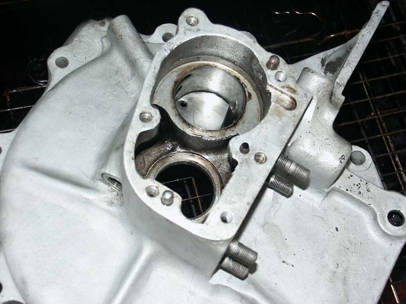
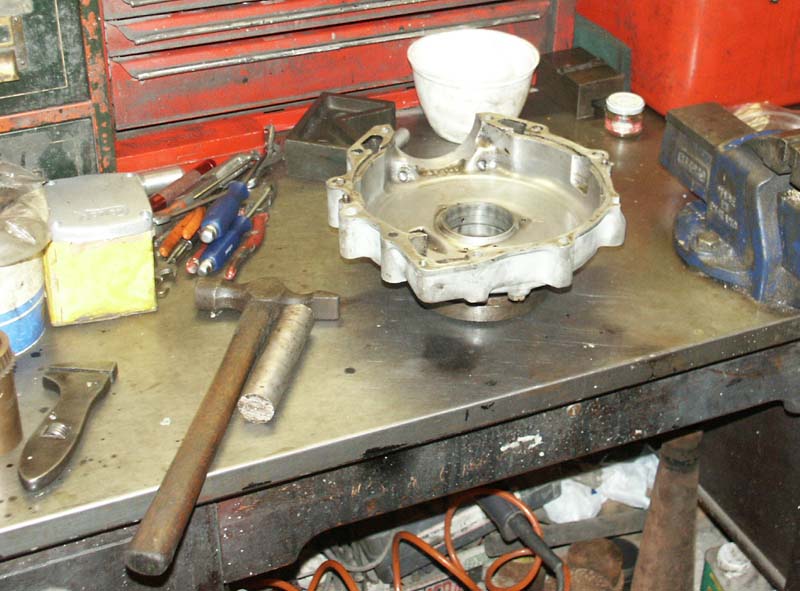
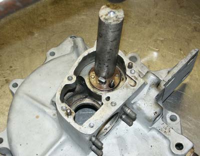
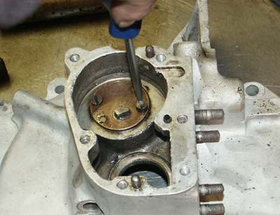 Removing the two
screws that retain the oil pump. Unfortunately the
pump did not then magically jump out and a trip
to the oven and a small amount of force was necessary
Removing the two
screws that retain the oil pump. Unfortunately the
pump did not then magically jump out and a trip
to the oven and a small amount of force was necessary
|
|
|
|
|
|
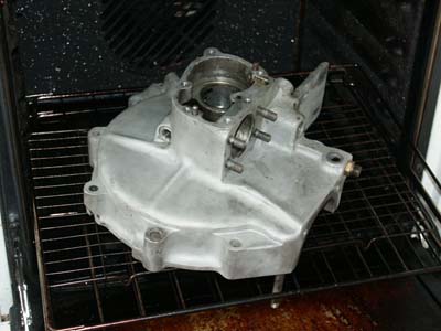
In
the case of this engine, removing the oil pump first meant removing
the two retaining screws then placing the crankcases in the
oven to get them good and hot. Sometimes once hot the pump will
drop out of its own accord, but in this case that did not happen,
and therefore further encouragement was required. Sometimes
you may be lucky and find the body of the pump has been threaded
so that studs can be screwed in and a 1” x 6” placed
over the timing case, to act as a puller by screwing nuts along
the studs. In this case unfortunately the oil pump was not threaded
and even with the crankcases ‘spit’ hot (stick head
in oven and spit at crankcases. If the spit bounces back at
you the crankcases are hot enough – use thick ovengloves
or rags to remove crankcases, they are now very hot!) the oil
pump was showing no signs of movement.
|
|
|
|
|
|
|
|
|
|
|
|
|
|
|
|
|
|
|
|
|
|
|
|
|
|
|
|
|
|
|
|
|
|
|
|
|
|
|
|
|
|
|
|
|
|
|
|
|
|
|
|
|
|
|
|
|
|
|
|
|
|
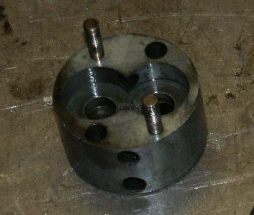
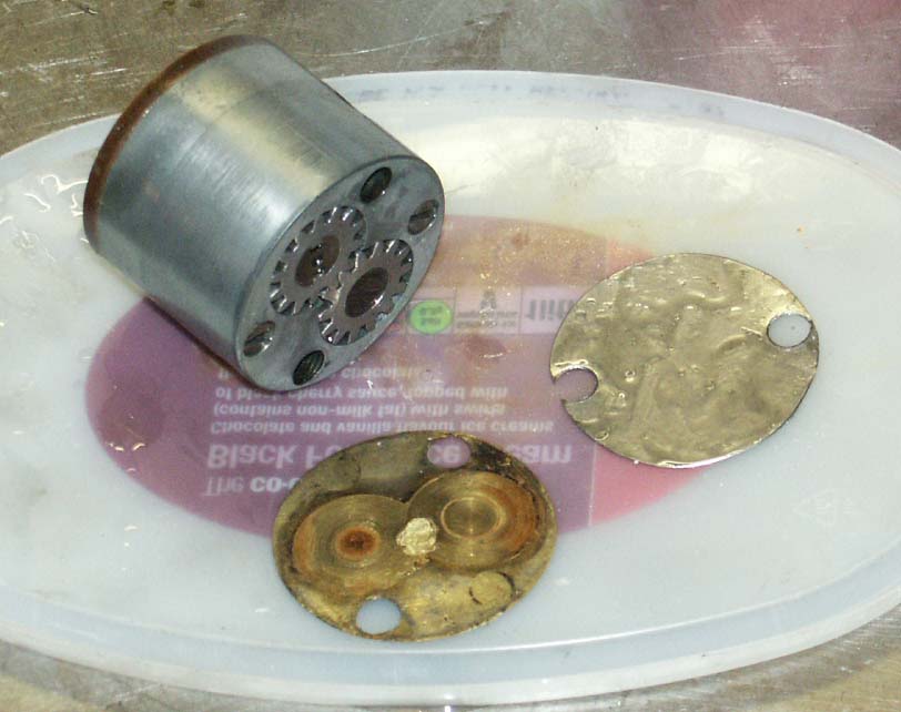
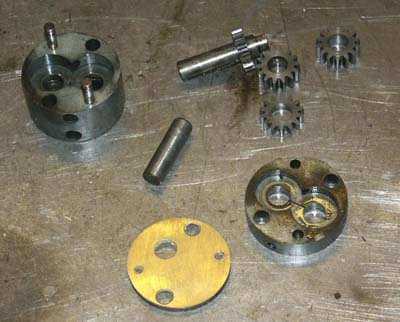 The pump finally
removed and stripped to its component parts
The pump finally
removed and stripped to its component parts
|
|
Getting it Out
. . .
As with many Inter crankcases, there was a hole drilled behind
the oil pump to assist with removing the pump, if all else fails,
this allowed me to use a small drift, to tap the oil pump out
from behind. It was actually in quite hard and therefore I had
to use far more force than was ideal, and with each bang of the
hammer I had visions of the gears crunching, or the monkey metal
body deforming, as the steel punch drove home. Luckily, I could
see there was a brass plate behind the pump - a common thing to
find, it stops the backgears wearing against the crankcase wall,
and hopefully this would take the brunt of the force
Eventually, after what seemed a long and painful period of time,
the pump had loosened off to almost drop out the last half an
inch and I breathed a sigh of relief. As expected the punch had
done a little bit of damage, just catching one of the back gears,
but this was not serious and was carefully bought back to shape
with judicious use of a swiss file. I was pleased to find no serious
scores or gauges in the body, and although the gears had a slight
sharpness on one end, they also looked in generally good condition
with no nasty notches or damaged teeth – so often the case
when a piece of foreign debris has made its way through the pump.
|
|
|
|
|
|
|
|
|
|
|
|
|
|
|
|
|
|
|
|
|
|
|
|
|
|
|
|
|
|
|
|
|
|
|
|
|
|
|
|
|
|
|
|
|
|
|
|
|
|
|
|
On
that subject, a mildly amusing story comes to mind. A few years
ago I saw advertised a collection of oil pump parts. The price
was not excessive so I took a punt and bought them without seeing
them (I should have known this would be a bad move, as I had an
idea who the seller was and thought this might be their cast off’s).
When they arrived there was a collection of oil pump parts that
would originally have compromised approximately 8 – 10 pumps.
Of these 100 - 150 parts, I don’t think there were more
than 2 to 3 of them that could be in any way classed as usable!
Of the others, I have never seen such a rotten collection of scrap
in my life. Every pump body showed heavy score marks and gauges
in the areas surrounding the gear wheels, where lumps of debris
had been forced round the pump under duress! The gears were all
chewed and even some of the shafts looked bent. What it does illustrate
is that you should not take it for granted that the pump will
be ok, even if it is capable of turning. If the body is badly
chewed, or the gears damaged, it will seriously reduce the efficiency
of the pump.
In the case of this engines pump, I could see that the pump was
actually in very good condition, and as can be seen from the photographs,
there was no heavy scoring to the body. My normal process for
maintenance of an oil pump is first to meticulously degrease and
clean it, then loosely re-assemble it with clean oil. |
|
|
|
|
|
|
|
|
|
|
|
|
|
|
|
|
|
|
|
|
|
|
|
|
|
|
|
|
|
|
|
|
|
|
|
|
|
|
 As
can be seen, the sidewalls were in good condition
and relatively unmarked, which was nice
As
can be seen, the sidewalls were in good condition
and relatively unmarked, which was nice
|
|
|
|
As
is often the case, I found that the gears would not turn freely,
even after cleaning, so I spent the next hour very carefully
running a swiss file round each gear removing any signs of burrs
or high spots. By the way, it is important when stripping pumps
to ensure you note which way the gear sits, relative to the
pump body, so you reassemble in the same plane as you stripped
it. The reason for this, is that you can find that the gear
occasionally ‘flattens’ at the end it touch’s
the end plate, and therefore the gears become ‘sided’.
I confess I forgot to do this in this case, so had to be extra
careful when I re-assembled until I figured out which side went
where (you can sometimes see matching wear marks on corresponding
gears – I tend to use an eyepiece to check). After what
seemed a very long time, the gears were able to slide back into
the pump far easier and gently revolving the pump drive with
a suitable drive tang (an old oil pump drive plate is good for
this) gave that lovely satisfying feeling of gears revolving
smoothly together. The last step of the refurnishing process
was to take the brass side plate (the plate that the drive shaft
fits through) and remove the score marks where the oil pump
gears have been revolving. I first of all put this plate (carefully)
on my linishing machine, using a fine belt, until all traces
of the scoring are removed. I then put it on a surface plate
using fine wet and dry (with light oil sprayed on it) for the
final clean. |
|
|
|
|
|
|
|
|
|
|
|
|
|
|
|
|
|
|
|
|
|
|
|
|
|
|
|
|
|
|
|
|
|
|
|
|
|
|
Having
washed all parts again in the degreaser (and put an airline on
them all), I carefully reassembled for the last time, using lots
of clean castor oil. The oil pump body is in two parts, with the
small set of pump gears sitting in the smaller side. These two
bodies are clamped together with two screws. When re-assembling,
I just screw them together finger tight then spin the gears again,
while final tightening, to ensure everything finds its proper
place, to give the best operation. The final result was an oil
pump that felt totally different to the one that first came out,
and was lovely and smooth in operation, with lots of gurgling
castor oil passing through it – very satisfying! |
|
|
|
|
|
|
|
|
|
|
|
|
|
|
|
|
 I
forgot to take a 'before' photo, but there were
heavy score marks in the brass cover, made by the
pump gears. They were removed on my linisher, before
final wet\dry polishing on a surface plate
I
forgot to take a 'before' photo, but there were
heavy score marks in the brass cover, made by the
pump gears. They were removed on my linisher, before
final wet\dry polishing on a surface plate
|
|
|
|
|
|
|
|
|
|
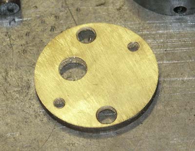
 Final
re-furbished oil pump, ready to go back in crankcase.
Old brass shim (bottom) was replaced with new steel
shim (right)
Final
re-furbished oil pump, ready to go back in crankcase.
Old brass shim (bottom) was replaced with new steel
shim (right)
|
|
|
|
|
|
|
|
|
|
|
|
|
|
|
|
|
|
|
|
|
|
|
|
|
|
|
|
|
|
|
|
|
|
|
|
|
|
|
|
|
|
|
|
|
|
|
|
|
|
|
|
|
|
|
|
|
|
|
|
Re-Fitting
Pump and Main Bearing – Timing Side
Obviously, the thing to get right when refitting the oil pump
is to ensure you get it in in the right location, as it is cylindrical
and there are no guiding channels. As this pump was so difficult
to remove, I also knew I would only get a couple of seconds before
the heat in the crankcase transferred to the oil pump and everything
locked up! To help with this process I use a very simple tool,
this being a shaft the same diameter as the securing screws, with
a thread on one end and a slot for a screwdriver at the other
end. I screw this into one of the threaded holes in the crankcase
before I place the crankcase in the oven, so it provides a guide
for the oil pump to slide down, and ensures it must locate correctly
– simple. Once the oil pump is fitted, this can then be
removed and the proper securing screws can be refitted. This should
be done with the crankcases still hot, to ensure the pump is fully
bolted home, before the crankcases have cooled and ‘shrunk’
around the oil pump, locking it.
|
|
|
|
|
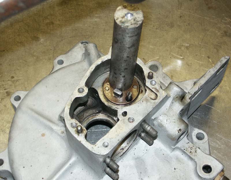
The
other thing I had to do before finally fitting the pump was to
make a new ‘backplate shim’. I am not sure if these
were fitted by Norton’s originally (I have seen crankcases
with gear wear marks on the backwall, so presumably they were
not), but it is not unusual to find them fitted, which to me seems
a good idea, and means the shim then takes any future wear, rather
than the crankcases itself (Not sure really why Norton’s
themselves did not design the oil pump to have a plate on both
ends). The one I removed from this engine was the normal brass
jobbie, but as I mentioned earlier, because I had to use a punch
to remove the pump, this shim had been badly deformed and where
the punch had hit it, there was a little circle of brass that
was almost broken away. I did not have any brass (used normally
because it is relatively soft), but did have some shim steel of
the same thickness, so got my scissors out and soon had a new
shim made that slotted in to the oil pump recess nicely. |
|
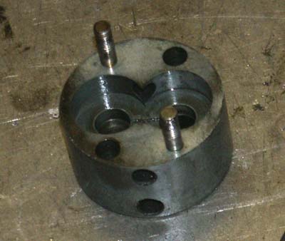
 Before
placing crankcase in oven, I screw in the oil pump
locating peg and drop the shim in to the base of
the pump housing
Before
placing crankcase in oven, I screw in the oil pump
locating peg and drop the shim in to the base of
the pump housing
|
|
|
|
|
|
|
|
|
|
|
|
|
|
|
|
|
|
|
|
|
|
|
|
|
|
|
|
|
|
 And
finally, place crankcase on a baking tray and cook
at full temperature until nicely browned, or spit
bounces off . . .
And
finally, place crankcase on a baking tray and cook
at full temperature until nicely browned, or spit
bounces off . . .
(just kidding)
|
|
|
|
|
|
|
|
|
|
|
|
|
|
|
|
|
|
|
|
|
|
|
|
|
|
|
|
|
|
|
|
|
|
|
|
|
|
|
 Having
dropped the pump into the hot crankcases, a firm
tap with an alloy drift ensures it is seated and
fully home
Having
dropped the pump into the hot crankcases, a firm
tap with an alloy drift ensures it is seated and
fully home
|
|
|
|
|
|
|
|
|
|
|
|
|
|
|
|
|
|
|
|
|
|
|
|
|
|
|
|
|
|
|
|
|
|
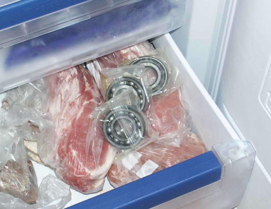
I
then placed the oil pump in a freezer bag and placed it in the
freezer, next to the main bearings I had already put in there
a couple of hours before. I don’t know about you, but I
often get a nose turned up, when I mention this to friends –
particularly friends wife’s! Similarly, when I talk about
placing crankcases in the oven to make them expand. I explain
to them that my engine parts are normally cleaner than the oven
I am putting them into, but this bit tends to fall on deaf ears!.
Luckily, I have a long suffering wife who is used to such things
(as was my mother, with my father before me), and her main bugbear
is that invariably I leave oily fingerprints on the freezer or
oven door!
|
|
|
|
|
|
|
|
|
|
|
|
|
|
|
|
|
|
|
|
|
|
|
So
with the timing side crankcase final cleaned, to ensure it was
spotless, I then put it into a really hot oven, while I prepared
the work surface of the bench, with suitable alloy drifts, hammers
and the large spacer rings I use to rest crankcases on, to provide
a firm surface to press against. Once the crankcase half was at
a suitable temperature it was just a case of working fast and
methodically. First the assembled oil pump was dropped in, ensuring
the shim was still in place and that I had got the orientation
correct (it is still possible to get the pump 180 degrees out,
even with a locating pin in place). I was pleased to feel that
the oil pump dropped almost all the way down immediately, into
its well, before I need to apply a light tap with a large alloy
drift, which ensured it was touching the back wall. Then quickly
I removed the guiding pin and replaced the two oil pump screws
that lock the pump to the crankcase body – job done. Final
step is to just quickly revolve the oil pump drive gear again
and ensure the gears still turn, again, do this with the crankcases
still hot, just to let everything seat correctly. |
|
|
|
|
|
|
|
|
|
|
|
|
|
|
|
|
|
|
|
|
|
|
|
|
|
|
|
|
|
|
|
|
|
|
|
|
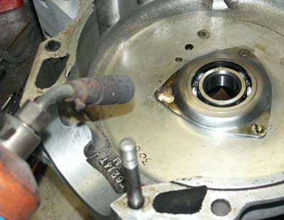
Fitting
the Timing Side Main Bearing
This only took a couple of minutes, so I tested the crankcase
and found it still very hot, so a quick dash to the freezer again
and I retrieved the timing side ball bearing and carefully removed
it from its protective packaging. As I knew the original bearing
had started to spin in its journal, using a Bearing Fit compound
on reassembly would be an essential. I quickly and carefully smeared
the outer face of the new bearing with this, ensuring it was evenly
coated across the full surface, then lined the bearing up square
above the crankcase journal, holding it by its inner race –
and dropped! I was rewarded by seeing it drop instantly all the
way into the journal, and hearing a slight clink as it hit bottom.
Just to be sure I placed one of my wide bearing drifts (i.e. the
drift only touch’s on the outer bearing race, not the inner)
on the bearing and gave it a quick tap with a mallet, ensuring
it was definitely seated fully home and square. Job done.
I then carefully removed the crankcase from the workbench and
placed it on a clean spot on the garage floor to let it cool down
a bit before I went back to put the bearing retaining plate on.
This is a difficult choice, as the retaining screws need to be
soldered to stop them from coming out, and to do this needs the
crankcases to be quite warm, as they act as a heatsink, stopping
the solder flowing freely, but I also wanted to give the crankcases
enough time to cool and ‘grasp’ the main bearing,
before moving on.
I used the few minutes while I was waiting to place the drive
side crankcase in the oven, to repeat the process. |
|
|
|
|
|
|
|
|
|
|
|
|
|
|
|
|
|
|
|
|
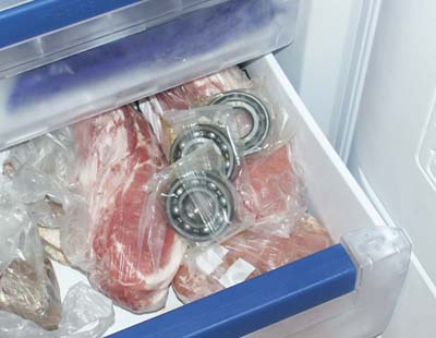 To
ensure the main bearings are as cold (and shrunk)
as much as possible, place them in the freezer at
least a couple of hours before fitting them
To
ensure the main bearings are as cold (and shrunk)
as much as possible, place them in the freezer at
least a couple of hours before fitting them
|
|
|
|
|
|
|
|
|
|
|
|
|
|
|
|
|
|
|
|
|
|
|
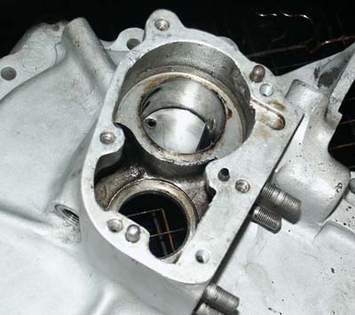
 Drive
side crankcase has just come out of the oven and
is placed on large steel spacer that supports the
bearing housing while bearings go in
Drive
side crankcase has just come out of the oven and
is placed on large steel spacer that supports the
bearing housing while bearings go in
|
|
|
|
|
|
|
|
|
|
|
|
|
|
|
|
|
|
|
|
|
|
|
|
|
|
|
|
|
|
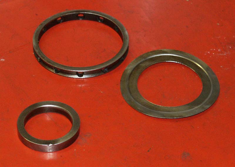
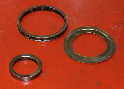 Drive
side spacers, that fit between ball and roller bearings.
Note large dished washer which is very rare to see
Drive
side spacers, that fit between ball and roller bearings.
Note large dished washer which is very rare to see
|
|
|
|
|
|
|
|
|
|
|
|
|
|
|
|
|
|
|
|
|
|
|
|
|
|
|
|
|
|
|
|
|
|
|
|
|
|
|
|
|
|
|
|
|
|
|
|
|
|
|
|
|
|
|
|
|
|
|
|
|
|
|
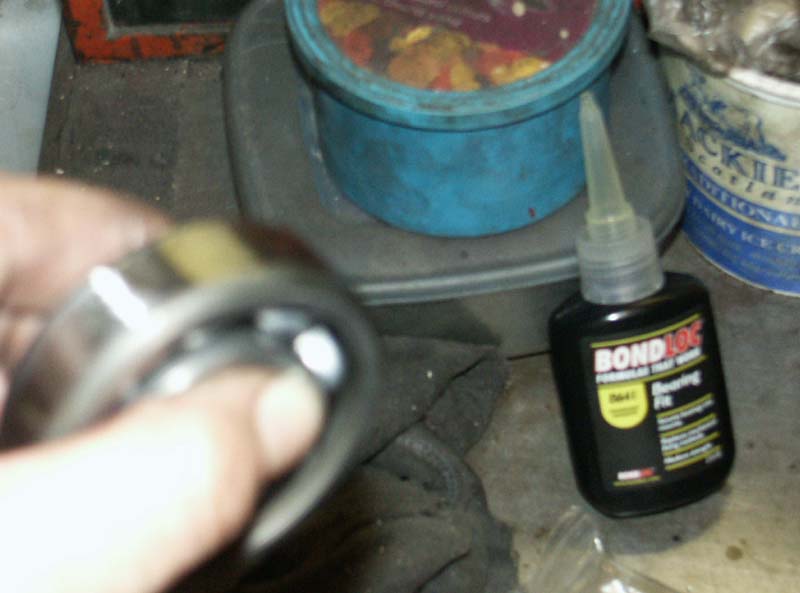
 Before
dropping each bearing in I applied a liberal smear
of Bearing Fit Fluid to the bearing outer wall.
Apologies for blurred photograph but I was in a
bit of a hurry!
Before
dropping each bearing in I applied a liberal smear
of Bearing Fit Fluid to the bearing outer wall.
Apologies for blurred photograph but I was in a
bit of a hurry!
|
|
|
|
|
|
|
|
|
|
|
|
|
|
Drive
Side Bearings
For the drive side, fitting new main bearings is pretty much straightforward
and relatively simple. The only points to be aware of, are to
ensure that the outer and inner spacers are fitted between the
ball and roller bearing. The ball goes in first (I do it with
the writing on the bearing facing me, not sure if this makes a
difference, but I remember being told many years ago this was
the face you should hit, if having to drift the bearing in). Then
the outer bearing spacer, with the holes drilled in it (to ensure
oil flows to the outer bearing in operation), then carefully and
quickly place the smaller inner spacer on the inner race of the
ball bearing.
Finally the roller bearing is removed from its packaging and dropped
in, ensuring the lip is innermost (you are using a lipped roller
aren’t you??, I have stripped a few engines where these
have not been used, but they should be). Final step is again to
use the bearing drift to ensure the bearings are fully seated
and square, and again I was rewarded with that slight metallic
sound, telling me the bottom bearing was touching the bottom face
of the crankcase journal. Good stuff.
Again, with both bearings I had decided to be safe and use Bearing
Fit compound to ensure the best possible chance against spinning
the new bearings.
As with the timing side crankcase, I now placed these onto the
garage floor and put a small piece of clean cloth over the bearings
themselves, to ensure no bits of crud got in while I was working
on the other crankcase. |
|
|
|
|
|
|
|
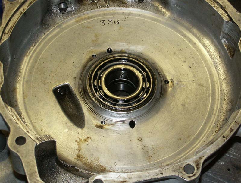
 Drive
side bearings now fitted. There is something about
the look of brand new bearings smothered in hot,
clean castor oil that cannot be beaten!
Drive
side bearings now fitted. There is something about
the look of brand new bearings smothered in hot,
clean castor oil that cannot be beaten!
|
|
|
|
|
|
|
|
|
|
|
|
|
|
|
|
|
|
|
|
|
|
|
|
|
|
|
|
|
|
|
|
|
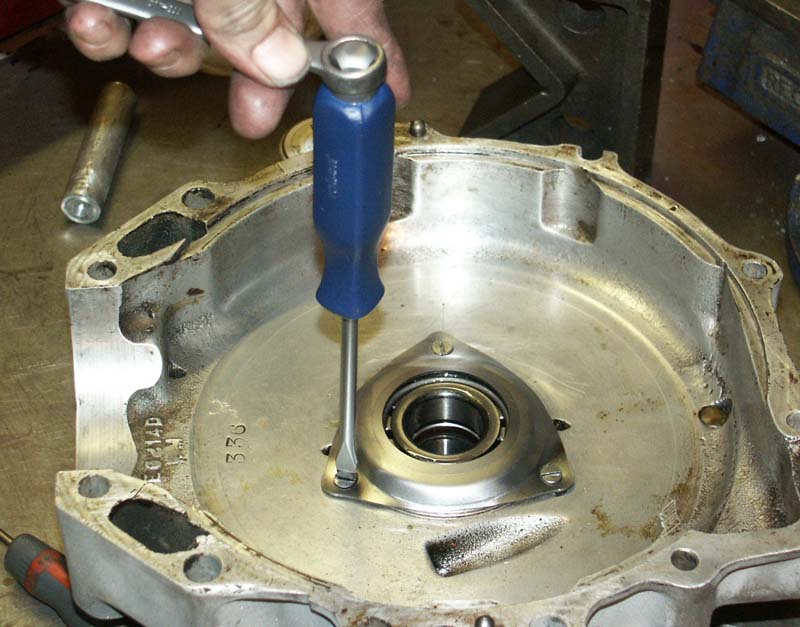
 Fitting
new bearing plates and screws. I am using a screwdriver
with the facility to take a spanner, to give extra
purchase
Fitting
new bearing plates and screws. I am using a screwdriver
with the facility to take a spanner, to give extra
purchase
|
|
|
|
|
|
|
|
|
|
|
|
|
|
|
|
|
|
|
|
|
|
|
|
|
|
|
|
|
|
|
|
|
|
|
Fitting
the Bearing Retainer Plates
Once the bearings have been fitted in the drive side crankcase
I can revert my attention back to the timing side crankcase, which
has now cooled down sufficiently for me to touch it without a
cloth, although still quite warm. First of all I check the bearing
by lightly spinning its inner race and am glad to feel that although
still far from cool, the outer bearing race looks to be quite
firmly held. Now for fitting the bearing plate, which is held
by 3 countersunk screws. Even though the bearing plate is brand
new, I still degrease it and remove any trace of dirt, ditto with
the screws themselves, which I also just put up against my rotary
wire brush (despite advice from my old friend Arthur, who tells
me this is not good practice for soldering.
Anyway, the bearing plate is fitted, with each screw being loosely
screwed in first, to ensure there is no chance of cross threading
any of them, before tightening each in turn. I use a screwdriver
which has a facility for a screwdriver to be put on it, to get
them in quite hard. Finally, I give each screw a tap with an impact
driver before soldering over the heads.
For those that have tried this process, you might find it is quite
difficult to get the solder to run freely on the heads and bearing
plates. I have found this is invariably because the crankcases
are not hot enough and are just absorbing heat. Having already
warmed the crankcases up, and using new plates and screws, I found
the solder ran quite freely and easily. I use a good quality soldering
flux and place a bit of this on both screw and plate corner first.
The other thing to be careful of when soldering is to ensure that
once the solder has flowed and you have let it cool, you are very
careful to remove any loose solder that has spattered, so it does
not go into the bearings or any of the oilway’s, this is
much easier to do than you may think. By the way, I have tried
soldering irons to do this task, but have never had much luck,
so I use a butane torch, which seems to work well. |
|
|
|
|
|
|
|
|
|
|
|
|
|
|
|
|
|
|
|
|
|
|
|
|
|
|
|
|
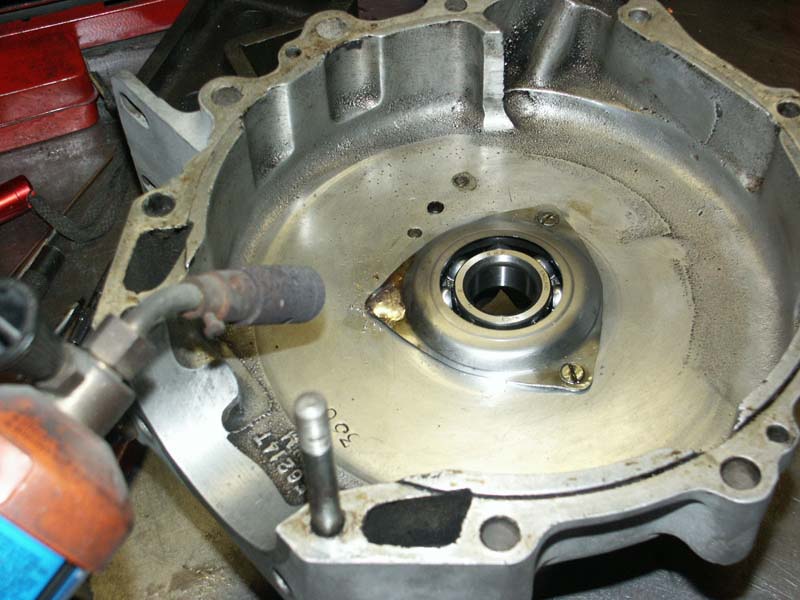
 Final
job is to solder over each bearing plate screw,
so they cannot work loose in operation
Final
job is to solder over each bearing plate screw,
so they cannot work loose in operation
|
|
|
|
|
|
|
|
|
|
|
|
|
|
|
|
|
|
|
|
|
|
|
|
|
|
|
|
|
|
|
|
|
|
Well,
that about does it for the main bearings and oil pump. I have
to say, I am always pleased when I have got these two jobs done
and I can relax a bit. Next stage will be to complete the bottom
end assembly, shimming the crank and fitting lower bevel housings
etc, and I will cover this in my next update shortly.
For the moment, I need to go and fettle the doubleknocker ready
for my annual trip to Mallory 1000 Bike Festival, so it may be
a little while until this engine gets another look in.
|
|
|
|
|
|
|
|
|
|
|
|
|
|
|
|
|
|
|
|
|
|
|
|
|
|
|
|
|
|
|
|
|
|
|
|
|
|
|
|
|
|
|
|
|
|
|
|
|
|
|
|
|
|
|
|
|
|
|
|
|
|
|
|
|
|
|
|
|
|
|
|
|
|
|
|
|
|
|
|
|
|
|
|
|
|
|
|
|
|
|
|
|
|
|
|
|
|
|
|
|
|
|
|
|
|
|
|
|
|
|
|
|
|
|
|
|
|
|
|
|
|
|
|
|
|
|
|
|
|